Continue to Site

Eng-Tips is the largest engineering community on the Internet

Intelligent Work Forums for Engineering Professionals

  • Congratulations KootK on being selected by the Eng-Tips community for having the most helpful posts in the forums last week. Way to Go!

Truss bearing point at interior? 3

Status
Not open for further replies.

EngStuff

Structural
Jul 1, 2019
81
I want some opinions on this truss. It's an existing residential cathedral truss that spans only 30 feet. I am 99% sure that the reactions are on the outsides only, especially 30 feet isn't that long for a truss to span to both of its ends. The part I am unsure of is because of a vertical web that runs straight to an interior wall. That being said, just because it has a vertical web on top of a wall, doesn't mean it is a bearing point. I have designed trusses that have similar configurations with 2 bearing points on its ends only, but I have also designed similar configurations with 3 bearing points with one in the interior. Not saying I am a pro when it comes to designing trusses, but enough times to have an idea of what can or can't be done, but not enough times to not get stumped on this situation. Though I still think it's not load bearing. There is no gap, but I've seen many times that contractors don't leave gaps between truss bottom chords and top of plate members for partition walls. Also, maybe they did leave a gap, but as years went by, it sagged to the point that it's bearing on the wall, but not enough to cause any structural or serviceability issues. I did not see any "crushing" on the top plate (didn't check all locations).

What I unfortunately can't check is if the wall is sitting on a beam or joists below it. If it's on joists that are 2+ feet away from the support, then I would ultimately assume not load bearing. If the wall was on a beam, i would still be unsure at that point. Until we get a chance to go into the crawl space (have to create a hole somewhere which adds more time and cost, and would like to try figuring it out before we go that route)
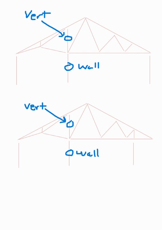
Truss_paquvw.jpg
 
Replies continue below

Recommended for you

For a 30' span, I would think it is likely to only be bearing on the exterior walls.
 
For the truss, the wall is not a support. But for the wall, it might feel the load imposed by the truss after erection, because at the time of erection of the wall, the truss might not have experienced its full load
 
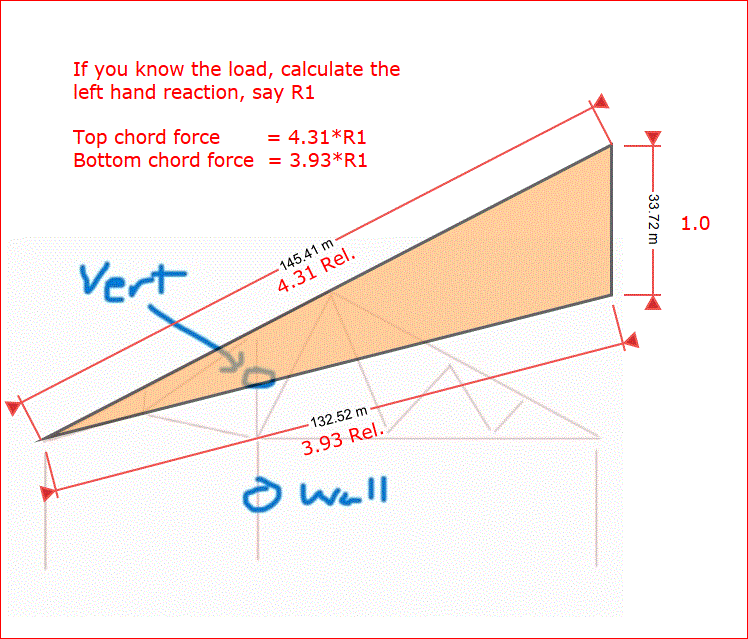
If your sketches are drawn to scale, the angle between top and bottom chord on the left looks a bit shallow. The sketch below gives a rough idea of the chord force, assuming you can calculate the left hand reaction. Check to see if the chords are okay (make sure to check the connection as well).

If those two chords are adequate, it should be safe to assume the wall is not required for strength. That does not mean it will not take load. If they are touching, it will. It just means you are not relying on it.

Capture_tbf5rq.gif


BA
 
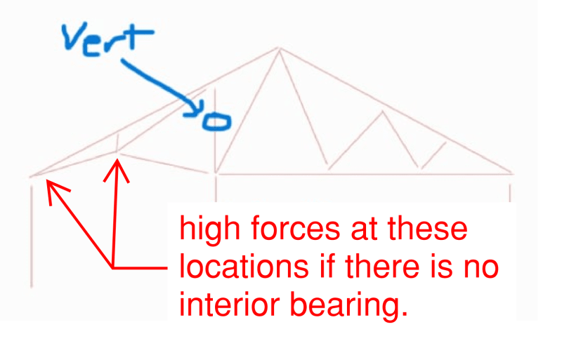
If the sketches are close to scale, then I feel that this could break either way. 30' is a modest span for a flat bottomed truss. However, per the sketch below, you can expect some considerable forces to be coming into the highlighted joints in the absence of that intermediate bearing.

Were I designing a run of trusses like this and had I the option of using that bearing wall, I would certainly be tempted to do so. You'd be saving $$ on the plating costs of those two joints and, over the course of a bundle of trusses, might save a few hundred dollars.

If you can supply photos or sketches of the two highlighted joints, we can probably make a more educated guess on the intermediate support intention.

C01_vewgqi.png
 
BAretired said:
If your sketches are drawn to scale, the angle between top and bottom chord on the left looks a bit shallow. The sketch below gives a rough idea of the chord force, assuming you can calculate the left hand reaction. Check to see if the chords are okay (make sure to check the connection as well).

We had ran a quick analysis, but the measurements were approximates. I will get more info soon and run a more thorough analysis on the project.

Kootk said:
If you can supply photos or sketches of the two highlighted joints, we can probably make a more educated guess on the intermediate support intention.

I will get that information soon too.

We will also try to take pics at all the Joints*. sometimes it's just hard to get around certain attic locations. It is very difficulted to get to that location, because of the tight spaces, but i think we can make it happen.

EDIT: incorrectly wrote Joists* instead of Joints*
 
I have designed trusses since the 1980s.

As already noted, 30' is not a large span. It's not likely that the wall was picked up for bearing. And a vertical at a joint does not in itself indicate bearing.

When the truss design program auto-webs a truss, they like to stick verticals in at all of the joints. It's possible that trusses was just auto-webbed and the pattern was not altered by the designer.

A couple of suggestions - One is to look at the heel plate. If they're something like a 3X4, then I'd lean strongly towards thinking the truss was designed to have bearing at the interior wall. If the heel plates re larger, then it's much more likely it's clear span.

Is there anything under that wall? If there isn't a beam or bearing wall under it, then a it's extremely unlikely that it was used for bearing.
 
If the truss and wall are connected, the wall is a bearing wall, intended or not.
 
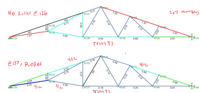
I got exact measurements and did a full analysis. The Truss is failing in my analysis.

On site I stuck a very thin metal strip between the truss and wall. Two trusses had a small gap between them. All other trusses were bearing on half of the top plate, close to one edge.

Went into the crawl space and the wall looks to be about 32" away from the center beam.

My opinion is that the wall is not an intentional load bearing wall, and is helping resist the load, I would say my analysis confirms it. what do you guys think?

Also, i couldn't get a picture at the one joint that was requested, spaces was extremely tight.

[URL unfurl="true"]https://res.cloudinary.com/engineering-com/image/upload/v1651459751/tips/Truss_Analysis_p3gtor.pdf[/url]
 
Other's opinion is not important when the truss fails your analysis. Important is what was the scope of this job.
 
I think you are correct, so whether or not it was intentional, the wall must be capable of safely sustaining the truss reaction.

BA
 
Can you tell us a bit more about the way in which the truss is failing in your analysis? I actually find that EOR's tend to struggle at modelling these kinds of trusses. The truss industry has it's own modelling standards that:

1) tend to produce more realistic results than conventional models in complex areas like heel joints etc and;

2) often help alleviate the things that will tend to fail in the EOR analyses.
 
If it is 32" away from the girder, it is unlikely to be load bearing.
 
Another thing to consider - run the analysis with dead load and 10-25% roof live load. That's going to be more consistent with what this truss sees on a daily basis. So if it's failing at full dead and live load with snow or wind...well the truss has probably never seen that. Of course that's not to say it's okay...it needs to be capable of handling those worst case scenarios...but it's important to understand how the truss has been working for all these years.

Also, make sure your allowable stresses are consistent with those at the time of production of the truss, not current values (current values are not retroactive but are reflective of changes in the mean strength of products coming out of mills over time - except tension if it's pre-1965ish, that was subject to an inaccurate test methodology, but metal plate connected trusses were still in their infancy then).
 
Pin-roller support is almost always assumed by the truss supplier and is appropriate in the majority of cases. Basically, no matter how many vertical supports you have, you only want one of them to be pin-pin. The rest should be pin-roller.

C01_h1xazd.png
 
BAretired said:
I think you are correct, so whether or not it was intentional, the wall must be capable of safely sustaining the truss reaction

I think I'm going to have to go this route, I analyzed multiple different ways, and shaved off a lot of load and still couldn't get it to work without the "wall" in my analysis. I really hate to have them add beams and columns throughout the location.

XR250 said:
If it is 32" away from the girder, it is unlikely to be load bearing.

I thought about this, but with every type of way I am analyzing the truss, it's failing. So what I think is, that the truss did give way. The walls did help relieve some load, but not a lot to cause sagging of the floor joists. the floor joists run perpendicular to the wall.

KootK said:
Can you tell us a bit more about the way in which the truss is failing in your analysis?

The way i model wood trusses is to release the bending moment at one or both of the individual members ends, but i am familiar on how to do it where it does not cause stability issues. so essentially each member only sees axial force transfer, however they do see center moment due to the distributed dead and live load.

For the Pin-Roller support. In this particular Truss I pinned the left side, placed a roller on the right side. The node on the right does have a moment fixity on the Y-axis and x-axis. This is for stability reasons. However, the Support is only seeing the Y reactions. no moments or other reactions. I had double checked the reactions to make sure.

A possibility which i don't like to do is to take the distributed load and make them into point loads and place them at the joints. I don't like doing that because i feel as it's not the "appropriate way". But that helps members resolve the "Bending & Axial compression failure mode". btw, i did resort to checking it both ways. The screenshot i provided is with distributed loading. what i didn't provide is a screenshot of placing point loads at the nodes, when doing it that way, I am still having a failure of the truss. The top left 2 cords show NC similar to the truss T1. also, the bottom left slopped chord is over stressed at 1.09.

phamENG said:
run the analysis with dead load and 10-25% roof live load

I ran it with a snow load of 17.5 psf because i didn't think it was necessary to run it with a live load of 20psf. I didn't check using wind load on the truss.

phamENG said:
Also, make sure your allowable stresses are consistent with those at the time of production of the truss, not current values (current values are not retroactive but are reflective of changes in the mean strength of products coming out of mills over time - except tension if it's pre-1965ish, that was subject to an inaccurate test methodology, but metal plate connected trusses were still in their infancy then).

It was built in the early 1980's, but this is good to know for other projects, is there a paper or a report name you can provide that i can find online or if you have one on hand?
 
If you're getting a NC check for the chords, it feels to me you don't have your unbraced lengths input correctly. Having those input correctly for both bending and axial could have a significant impact on the code checks.
 
jayrod12 said:
If you're getting a NC check for the chords, it feels to me you don't have your unbraced lengths input correctly. Having those input correctly for both bending and axial could have a significant impact on the code checks.


for the top chord, I have Le2 and Le-bend-top as 1 ft... Le1 and Le-bend-bot shouldn't matter in this case in my opinion because all my chords are modeled as individual members.
 
Normally Risa will tell you why there's an NC code. What does it say when you open the detailed member results?

What do you have the failing bottom chord un-braced lengths noted as? The same?
 
If it's from the 1980s, you should at least be using pre-2013 values. (Assuming it's southern pine, anyway). If you search for information on the downgrade of southern pine in 2013, the SPIB has a lot of information. As for the tension stuff, I don't have anything handy - just remember reading about it. As I recall the tension values were just based on flexural tension, which is actually unconservative for wood. Somebody figured that out and started to pure tension tests which lowered the tension capacity of lumber sometime in the late 50s or mid 60s.
 
Status
Not open for further replies.

Part and Inventory Search

Sponsor