Eng-Tips is the largest engineering community on the Internet

Intelligent Work Forums for Engineering Professionals

Tube support problem 4

Status
Not open for further replies.

Mfr1003

Mechanical
Jul 18, 2024
1
0
0
US
I’m a welding tech, so this problem is beyond me.

I’d also like to put this into Excel so I can set different variables and decide how much something can weigh or change the length, etc.

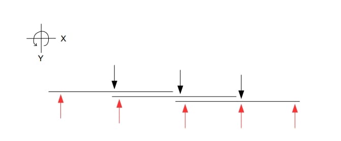
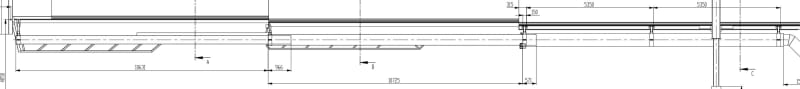
A three-stage telescopic tube is suspended from a total of five mounting points. The tubes are guided by rollers on the inside and outside. The weight of the inner tubes is also transferred to the next outer tube via the rollers.
We need the maximum weight that can be achieved per attachment point. The added total weight will be higher than the complete weight of the entire telescopic tube, as the weights shift depending on the position.

Weight of tube A = 445Kg
Weight of tube B = 575Kg
Weight of tube C = 745 kg

Feel free to ignore the numbers, I’d like to just figure out how to calculate this with symbols for now.

Thanks in advance! I’m just trying to learn something new. This isn’t from a course, I’m just trying to figure out how to solve a manufacturing problem, I’m not sure I have enough info.

IMG_4377_aeivh3.jpg
|

[URL unfurl="true"]https://res.cloudinary.com/engineering-com/image/upload/v1721324559/tips/IMG_4375_zdveih.jpg[/URL]|

[URL unfurl="true"]https://res.cloudinary.com/engineering-com/image/upload/v1721324559/tips/IMG_4376_ny34ui.jpg[/URL]
 
Replies continue below

Recommended for you

You're getting into an area that will require a good understanding of load and moment calculations.

Something tells me we should also ask this question: The diagrams lead one to believe this mechanism is suspended from some structure above.
1) Is it in fact suspended from an overhead support, possibly a ceiling or some framework?
2) This leads to the next question - Will people be working in, around, or underneath this system? If so, your recommended safety factor (and potential liability) just increased significantly.

In telescoping systems, the retracted state is usually the least problematic. So, you should do all your load calculations in the fully extended state. You will have to look at each individual segment to analyze the forces, moments, centers of mass of each body, and reactions at each individual support point. And of course, those factors add up as you proceed from the smallest tube to the largest.

Get some competent and experienced help.
 
As a "welding tech" you realize that you are not a Structural or Mechnical Engineer, .... right ?

So, you want us to slap something together into an EXCEL spreadsheet ....right ?

.. and we wont get paid ..... right ?

.... and if there is an honest error, and someone gets hurt ... there will be no legal consequences for us .... right ?

.......and we should trust nameless, faceless strangers ....... right ?

Your thoughts ?


MJCronin
Sr. Process Engineer
 
OP,
Thanks in advance! I’m just trying to learn something new
I applaud this! and I think most if not all the folks here would be happy to help you learn engineer concepts and science BUT as the others have stated, if this is for a design, it appears you are totally out of your depth. If this is for your personal education only, then hopefully me or others can put you on a correct path.
Since I do not know your aptitude or educational (formal or nonformal) background, I have no idea whether you can work through this but if you learn the following terms and concepts, they should give you enough information as to how to view the system and where and how the weight is being distributed. For future postings, you might want to consider the student forum because that is essentially what you are acting as from a question standpoint.

From what I think you are asking, you have two states, retracted and extended and you would like to understand how those two states effect the loading on the attachment points.

Your goal is to come up with a spreadsheet where I assume you can input a % extended or whatever and be able to see the loading on each attachment point. This is possible once you understand how to do it.

You are not considering dynamics, which is what happens when the system moves and would have to be part of the design to understand the system and the attachment points, but even if an engineer was going to do a dynamic analysis the starting point would be if it wasn't moving.

As an aside: If you already know all these things, then I in no way mean disrespect for framing it so basically but from what I read from your posting, you do not understand these concepts yet.

If you only want to consider where and how the weight is distributed then, in physics or engineering, this is considered a static analysis. The first concept you will need to learn, is how to draw a free body diagram. Please look up all of these terms because other will likely communicate these concepts better than me.
So, terms to look up:
Statics, free body diagram, normal force, reaction force, distributed load, shear, moment.
And two statements which you will need to understand:
The sum of all forces
The sum of all moments

Your free body diagram should look something like below:
Screenshot_20-7-2024_163751__hatixs.jpg
 
to give you an idea ... say the extended tube above has a load on the LH end of P and is attached to "the rest of the world" at the two RH arrows (call them RH_left and RH_right). Take the view at face value, so that there are four (equal) spans between loads. The RH_left will be 4P and RH_right 3P (or more correctly -3P) ... these two forces balance the applied load "P" at the far LH end.

Depending on what this is about, you may be better off building and testing, or getting professional help. The critical feature in the design may not be obvious (and may be overlooked). I would start by looking at other telescoping rods you can buy.

"Hoffen wir mal, dass alles gut geht !"
General Paulus, Nov 1942, outside Stalingrad after the launch of Operation Uranus.
 
I recommend the OP hire a consultant. This is beyond the scope of this forum.
For example whT are the safety issues.
And the risk as noted before.
 
I applaud the OP's inquisitiveness - just because one doesn't have a degree in classical violin from Julliard doesn't mean that taking up the violin is futile. Maybe a little naive to ask for a spreadsheet, but certainly nothing wrong with wanting to understand the objects being created.
 
Can you provide more details regarding the support type/dimensions maybe even pictures or sketches? Also how many internal rollers/what type (part #, McMaster # etc). Also tube dimensions for each section. I’m willing to help you out, sounds like a cool project. Glad to see someone take some initiative and try to do something instead of sit on their thumb.

Also would be good to know loading those (as fall protection has different safety factors than general loading).
 
Status
Not open for further replies.
Back
Top