Eng-Tips is the largest engineering community on the Internet

Intelligent Work Forums for Engineering Professionals

  • Congratulations waross on being selected by the Tek-Tips community for having the most helpful posts in the forums last week. Way to Go!

twin engine crank behaviour. 9

Status
Not open for further replies.

ivanheow

Automotive
Oct 28, 2005
42
0
0
GB
[ponder]hello to the collective ,

i am constructing a twin engined 1940's type racer . the 2 engines are straight 6 jaguar lumps, aluminium block 4 litre 245 bhp engines . i am tentatively designing them thus ..

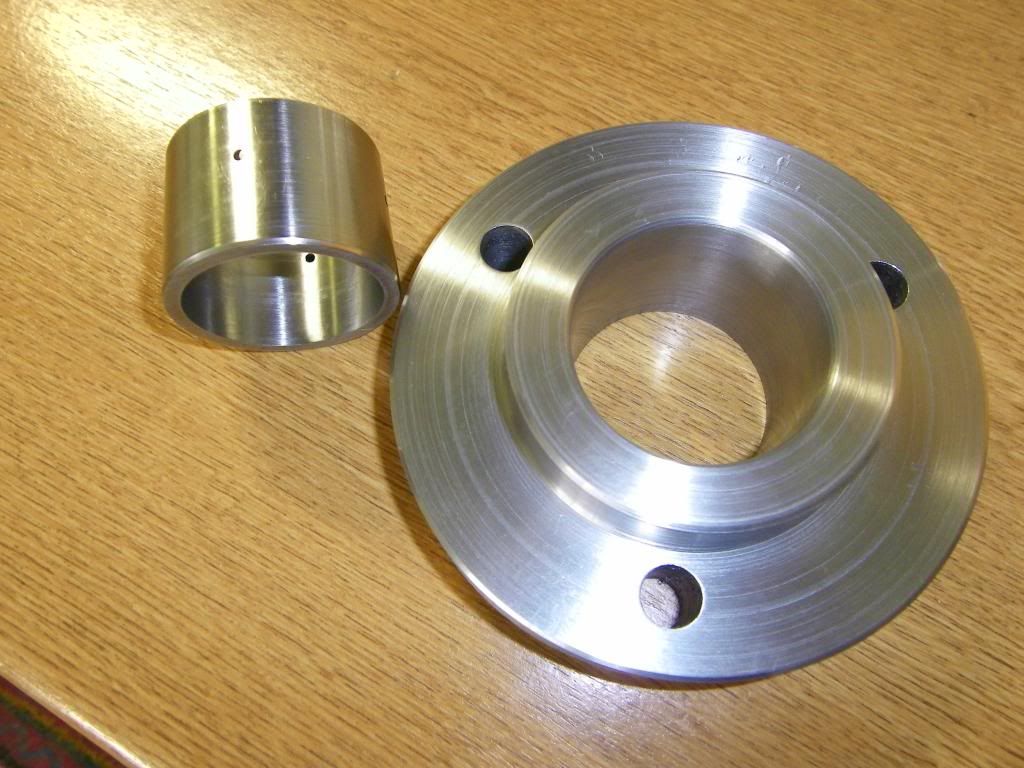
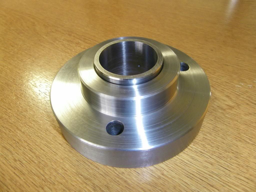
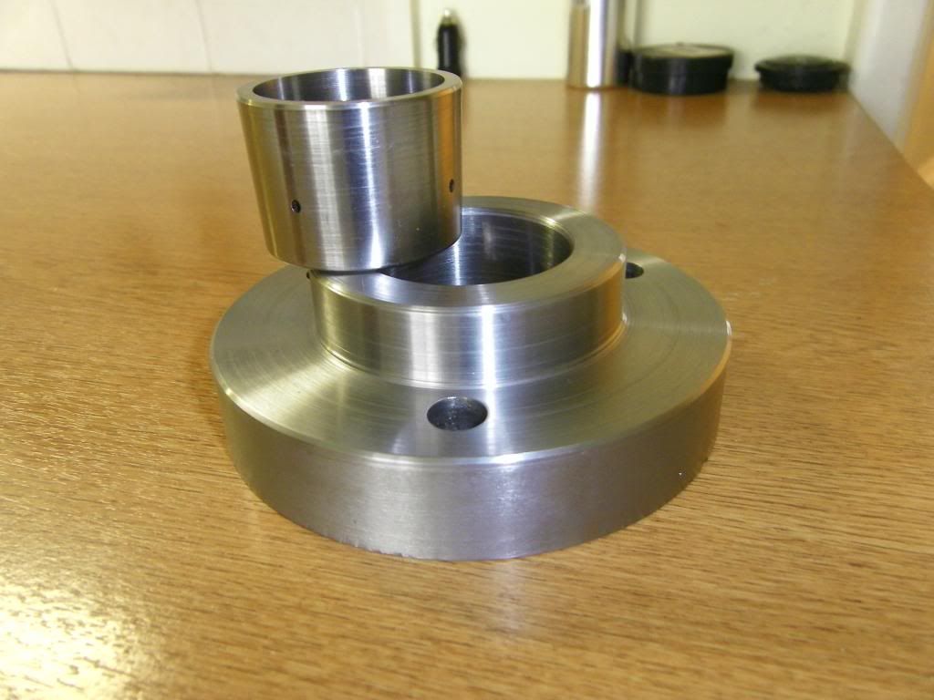
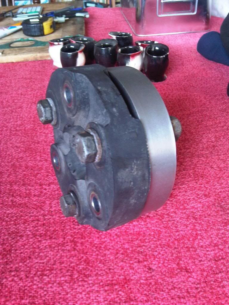
gearbox/clutch/flywheel unit(remote).........10" prop........uj mounted to crank end .....engine.........crank snout to 400 lb/ft jurid donut.............crank end......engine.....snout with stock crank pulley harmonic balancer .


so , i have gone from a trq converter on the end of each crank ,to a prop to a flywheel on one ,and a jurid donut on the other .and from a damper on each to a damper on one .
these engines tend to run very smoothly ,and have good balance as stock .

in the past i have converted a c4 auto to clutch ,created 2 gearboxes back to back ,and the fastest turbo minis use my bespoke clutch design .so have a little transmission experience , but not much on harmonics and acrrued vibration re no flywheel.


thoughts?

regards
robert


Replies continue below

Recommended for you

thank you johnny,
after doing a little more research into taper locking hubs , and thier trq handling capabilites i have knocked up a hub and taper as a sacrificial item to do further research with ..


i used an old mini primary gear for the taper collet ,1.5 degrees angle .

URL]


rrrattle034_zps96843d9a.jpg


rrrattle033_zps5d9cc8a9.jpg


rrrattle032_zpsfb58502e.jpg


IMG00233-20130415-1708_zps1c299686.jpg


working back from the taper lock hubs available ,and thier tech specs , this length and diameter of mating face would be good for around 1000 lbs/ft..... the taper used is not specified ,but i looked into this ,and decided to use similar to a morse taper ,which i think will be a fair bit stronger than the hubs available due to its being of a shallower angle , of course this will therefore require a very substantial puller to remove .

i'm still a little bit on the fence about whether to use a central locating spiggot or not .for and against comments greatfully recieved .
on the one hand , not having it would allow the engines to move a little bit more and not fight with each other .....on the other hand having a pin in the middle would keep the coupling from going into an orbital motion and them causing a big vibration , i know on my chassis dyno ,the coupling does not have a pin , but it is a lot bigger ,and also the two faces are bolted to pillow blocks and canonot really move , i am contemplating solid mounting the ends of the engine blocks nearest the coupling , leaving out the pin ,and very firm rubber mounting the furthur ends of the blocks ...that way the chassis flex will only affect the 10'' between coupling and hopefully be fairly minimal.

fun fun fun !


Any word how SireCustom's coupling and crank snout attachment have been holding up, and how many miles and holeshots have accumulated?
 
ivanheow-

If you can afford something semi-custom, take a look at some of the in-line engine couplings made for tractor pulling. These tractor pull components obviously are overkill for your application, but you can adapt the basic design for your engine coupling. And as I noted in a previous post, I would also highly recommend adding seals at each end of the spline joint so the teeth can be grease lubricated. This will greatly increase the spline life and reliability.

cranktocrankmounted.jpg


cranktocr1sm.jpg


Good luck to you.
Terry
 
Here is a Google search on gear couplings.

I've used these in industrial settings many times. They are extremely compact for their torque capacity. You are allowed several degress of 3d movement so in your case chassis deflection is not a problem. I think you could modify one of these relatively easy for you app.

A spin off of these has been used in the Fuel drag racing for over almost 50 years. It is a standard for coupling the transmission or final drive in the case of only having a reverse unit to the rear end. They very rarely fail. However they are special made from high strength materials.

Even though alignment is not too critical, when we build drag cars we use a line up bar to align the crankshaft with the pinion in the rear end so it is 0-0 and end play is limited by special shaft collars.

A passing comment on crank loads mentioned above. We use a very critical front cover on these motors that has a large roller bearing that is carefully fitted to run true with the crank centerline. The blower on the top fuel cars can take up to 800 hp to drive at the speeds they turn. The crankshafts are very special forging, I think 4340 alloy heat treated. They use a splined crankshaft with a mating hub that rides on the ID of the front cover bearing. The crank snout is about twice the diameter of a small block chev.....so it is very large.

My own streetrod has a 3" 8mm belt driving a 6-71 blower. I only use 8 pounds of boost so the load on the crank is not high. The front bearing is like new even after 20k miles. I actually don't use boost very often....the car is very fast even at 1-2 psi boost. I also only use a single stock key and a press fit hub with no balancer. (do not need it with the blower.)
 
Greg, saw a brm v16 up close and dirty 2 weeks ago - now that was crazy.
Making one engine of a matching set turn the other way hurts my head - mainly trying to convince yourself the cams just wont do no matter what. As with your case, went through all this before Christmas incl re doing oil drilling exit profiles on crank journals and the plug was pulled. Grrrrrr.

Brian,

ps, off topic, but a v8 maker that uses bike heads has a patent whereby he uses oem cams in both heads but turns one head. The left gets its chain drive from the bottom pulley as normal, but the right head is turned and picks up its drive from the flywheel end. He has an idler gear driven off crank which the chain drive is in turn taken off. This reverses the direction of rotation on the right head and its honky dory.
Using the oem head castings + cams/valve train keeps the cost down of finished engine to only' 35k and still allows users to buy cams from the aftermarket bike tuners that will fit right in.
 
Yeah, first time I saw directional polishing was in an old AE or Vandervell catalog maybe in the 70s. It was described as a possible cause of inserts worn into the copper/bronze.
It's everywhere now.

I was thinking other directionally significant details might be cam chain tensioners, machined seal labyrinths or even spiraled lips, and the location of single feed oil holes in rod journals.
 
The lapping is a good one - thanks. 'At least' thats one that you could just tell the engine re guys to ''run it the other way lads''
Finding space to put the timing belt tensioner because the tight run is now on the opposite side where the engine mount lies is something said guys dont want to hear about.
In hindsight, thank god it never saw the light of day - they wanted to keep the oil pump in its original buried location too

Brian,
 
The group I worked with at one of the Northrupp Grumman marine divisions had never heard of, nor was concerned with directional polishing. So it surprised me when they ignored direction when they did spend what I considered an inordinate amount of time improving the surface profile of journals >> 2 foot diameter by polishing with abrasive paper using a fitted back up block. They called it "superfinishing" , but in my mind superfinishing is, and will always be what Chrysler "invented" back in the 1930s.


Status
Not open for further replies.
Back
Top