Continue to Site

Eng-Tips is the largest engineering community on the Internet

Intelligent Work Forums for Engineering Professionals

  • Congratulations KootK on being selected by the Eng-Tips community for having the most helpful posts in the forums last week. Way to Go!

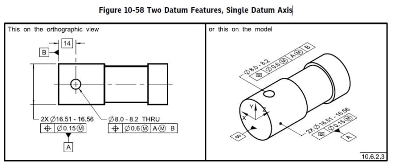
Two Datum Features, Single Datum Axis. 4
Status
Not open for further replies.

ASHWA

Automotive
Oct 7, 2020
52
Hi Friends,
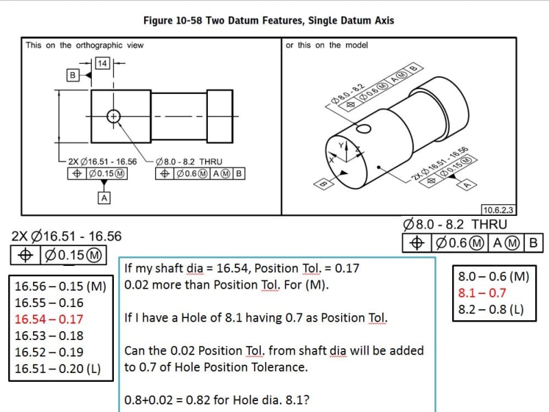
Need a help in reg. Two Datum Features, Single Datum Axis.
pos_cuvd3l.jpg


Is my assumption correct?

Thanks.
 
Replies continue below

Recommended for you

Pl. help in how to interpret the drg.

ddd_h0skco.jpg
 
I agree with 3DDave. One is the datum feature shift (datum feature mobility) and the other is the controlled feature.
It is more like a basketball hoope analogy.
The (M) on the left -close to 0.6- will make the ring smaller or bigger.
The (M) on the right -close to A- will just make the ring move slightly with no effect on its size.
 
Given the function of typical cross holes (retaining pin), applying MMC to the diameter seems counterproductive. As the diameter of A grows, there is a greater need for precision of the cross hole location.

Also, I don't understand how a position with no datums is valid.
 
TheTick said:
Also, I don't understand how a position with no datums is valid.

Because it controls the relationship between each other. You have 2X meaning two features (not just one).

Was not valid in 1994, but that was almost 30 years ago....time to upgrade.
 
ASHWA,
As mentioned above, the (M) for MMB (Maximum Material Boundary) applied to A in the Feature Control Frame allows for datum feature shift. It is NEVER a bonus, but it allows the datum feature to deviate from a simulator of fixed size and the part to "shift" when applied to the gauge. If your cross-hole comes in at 8.1 there is no more tolerance allowed than 0.6+(8.1-8.0) = 0.7, it cannot violate your virtual condition of 7.4 regardless of the size of A (ie: on a simulator a pin of size 7.4 fixed at basic location/orientation to datum feature simulator for A).

An excellent thread that breaks down the difference is (
TheTick,
Position's main "job" is to control location - whether to a specified datum feature or between features. As long as one or both of these are being accomplished then the control is valid.
 
Thanks SME's....

But, chez311 (Automotive),


How to calculate the shift?
 
ASHWA said:
How to calculate the shift?

In order to "calculate" the datum feature shift you do need the part to be produced and measured.
It is the difference between U/ RAME and MMB (VC)

Am I correct, chez311?

But since A is primary I guess UAME in this case (not RAME).

Please correct me if you would like.


The primary datum A constrains two rotational and two translational degrees of freedom. Referencing A at MMB will allow for a relaxation in those constraints such that some amount of rotation and translation is allowed between the datum feature and the MMB. The rotation/translation will allow for the feature Ø8.0 - 8.2 to be optimized within it's specified tolerance zone.

The amount of rotation/translation allowed will be dependent upon the part that is produced and is not a simple calculation like bonus tolerance.
 
Also keep in mind that if there's enough datum shift from A, then the face of the part will flatten out upon datum feature B. That means that some degrees of freedom normally constrained by datum A will be tackled by datum B instead.

John-Paul Belanger
Certified Sr. GD&T Professional
Geometric Learning Systems
 
Lacking a specific example in the 1994 version does not mean it was not valid. It was certainly used as a secondary entry in a composite FCF which means it was interpretable.

Berlanger - isn't having the end of the part flat against the datum simulator the nominal case? The inspection fixture for this is a blind hole that the part is dropped into with a sliding gage cross-pin. I expect that most quality shops would make parts such that they didn't need to touch the sides of the fixture and would rest on the flat.
 
3DDave said:
isn't having the end of the part flat against the datum simulator the nominal case?
While that would be the case for a perfect part, we have to consider the possibility of datum feature B being tilted. And the drawing does not give a tolerance relating datum feature B back to datum A (perpendicularity or a similar tolerance). So I don't think we can come up with a threshold number of when the part would be oriented by A vs. B.
It's like Fig. 7-20 (c) and (d)... If there's little to no shift, then the primary datum constrains the orientation of the part (figure d). But given enough shift, as in (c), the secondary datum becomes responsible for orienting the part.

John-Paul Belanger
Certified Sr. GD&T Professional
Geometric Learning Systems
 
If there is the maximum primary datum orientation shift then the secondary datum reference has no necessary orientation control. Of course it's all dependent on ratios of length and diameter and the control on orientation of datum feature B. No matter what, there will be overlap, but in the NOMINAL (aka PERFECT) case we can see that the part will rest flat on datum feature B and not need to contact the datum A feature simulator.

I don't have a copy of the latest, so I have no idea what pictures "we" put in it.
 
Thanks SME's,

Since iam in early understanding of terms, so getting to key concept takes time for me,

Jacob Cheverie (Aerospace),


can you please explain which are the 2 Rotation and 2 translation, anything with a simple sketch pl.?


can i know how pl.?
 
ASHWA,

Of the six available degrees of freedom (DOF), it's easier to mention which DOF a cylindrical primary datum feature does not constrain. It does not constrain rotation about it's own axis (1 DOF) and it does not constrain translation along it's own axis (1 DOF). All other DOF are constrained.

Referencing A at MMB will require the use of a fixed datum feature simulator (true geometric counterpart). This means that as datum feature A departs from it’s MMB [MMC size plus any applicable geometric tolerances (form for a primary datum feature)] it is allowed to translate and/or rotate within the MMB. The feature is dimensioned to the MMB of A, so if the MMB of A is larger than A, A has some “wiggle room” which can be taken advantage of.

Think of a pin inside of a larger sleeve. The pin can translate and rotate in ways that it couldn’t if the sleeve were a tight fit.

A more precise example: A cylindrical feature has an MMB of Ø1.2 and the feature is produced at Ø1.1. The feature can shift within it’s boundary by .050 in any one direction because that is half of the difference in size [(1.2 – 1.1)/2 = 0.1/2 = 0.05]. This shift is purely translational. Imagine that the feature is .445 in length. What is the maximum rotation angle allowed between the two cylinders? How would you quantify shift if it was rotated a partial amount and translated a partial amount? You can see that it becomes complicated.
 
Thanks Jacob Cheverie (Aerospace), for your effort...!!

So,
TGC for A will be Ø16.56+0.15 = Ø16.71.
&
"A" can rotate/Translate, when its value is less or equal to Ø16.56 (MMB) to place the Hole.

Is my understanding correct?
 
ASHWA,

You are correct in that the MMB will be Ø16.71.

It isn’t so much that deviation from MMC will allow “shift”, but rather once the two surfaces making up datum feature A are measured, they are allowed any available “shift” (together) within the Ø16.71 boundary. For example, the first surface may measure Ø16.54 and the second may measure Ø16.52 and they may be out of position with respect to one another by .008. There will certainly be some rotation/translation allowed within the MMB that can be taken advantage of to place the hole as you mention but the surfaces must shift together as one feature.

Belanger brings up an interesting point about the interaction with datum feature B "overriding" some of the established constraints.
 
3DDave -- If you have the 2009 version of the standard, it's like Fig. 4-21 (c) and (d)... If there's little to no shift, then the primary datum constrains the orientation of the part (figure d). But given enough shift, as in (c), the secondary datum becomes responsible for orienting the part.

in the NOMINAL (aka PERFECT) case we can see that the part will rest flat on datum feature B and not need to contact the datum A feature simulator.
Who says the part is going to be at NOMINAL (aka PERFECT)? Think beyond that a bit.
Consider if datum feature B is tilted a fraction of a degree; that end face may not rest flat (if there isn't enough shift) or it may rest flat. I'm pointing out that the orientation of the entire part is not driven by a specific datum in every case. Study the figures I referenced in the standard if you need a visual.

John-Paul Belanger
Certified Sr. GD&T Professional
Geometric Learning Systems
 
Status
Not open for further replies.

Part and Inventory Search

Sponsor