Continue to Site

Eng-Tips is the largest engineering community on the Internet

Intelligent Work Forums for Engineering Professionals

  • Congratulations KootK on being selected by the Eng-Tips community for having the most helpful posts in the forums last week. Way to Go!

Two Datum Features, Single Datum Axis. 4
Status
Not open for further replies.

ASHWA

Automotive
Oct 7, 2020
52
Hi Friends,
Need a help in reg. Two Datum Features, Single Datum Axis.
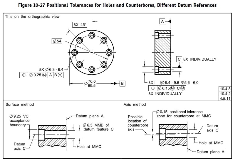
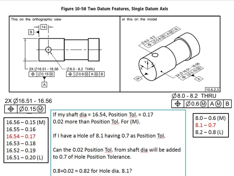
pos_cuvd3l.jpg


Is my assumption correct?

Thanks.
 
Replies continue below

Recommended for you

I take shift to mean between the datum feature and the datum feature simulator, not between one datum feature and another. The greater the shift of datum feature A, the less likely datum feature B is to be co-planar with its simulator. Also, unlike 4-21C, there are no bolts forcing planar contact.

For all I know a real part generally like the example has a convex end and can never drive orientation no matter what one considers shift to be. That means it can never be responsible.
 
Hi All,

Fig. 4-21 (c) in Y14.5-2009 is a classic example of a condition that is implied but not explicitly stated. As a cylindrical primary datum feature, A is responsible for constraining two rotations and two translations (including the CW/CCW rotation in the view shown). As a planar secondary datum feature that is nominally perpendicular to the primary, B is only responsible for constraining one translation (up/down in the view shown). B only needs to be in contact with its TGC at one point, as it is in 4-21 (d). Yet in 4-21 (c), B is shown in full contact with its TGC and effectively constraining rotational degrees of freedom. The question is: is there a requirement that B establish full 3-point contact with its TGC if it can? Or is full 3-point contact just one of many allowable candidate relationships? The fact that the figure shows full contact implies that this is a requirement, but there is nothing in the text that states this or addresses the issue at all.

The issue of "inherited constraint" can be exapressed as a more general question:

Q: If a higher precedence datum feature only partially constrains a degree of freedom it is theoretically capable of constraining, are the lower precedence datum features required to constrain that degree of freedom?

Here's a hypothetical scenario to illustrate the point. Let's say that the as-produced part in 4-21 (c) was made such that the 4 holes were nicely parallel to feature A, but skewed relative to feature B. The 4 holes were all made at MMC size and with some error in their relative spacing. The gage has 4 2.9 mm pins that the 4 holes have to fit over. Let's say that the 4 holes fit if feature B is in 1-point contact with its TGC and feature A is inside its TGC, but the 4 holes don't fit over the 4 pins if B is pushed down into full 3-point contact to constrain the rotational DOF's. Should I call this a nonconformance because I can't get the feature to pass with the part contacting the gage in the way that is shown in Fig. 4-21 (c)?

I would say that the answer is no. The feature satisfies the position requirement while feature A is inside its TGC and feature B is in 1-point contact with its TGC, so the feature conforms to the tolerance.

Short story long, I am saying that the condition shown in 4-21 (c) is allowable but not mandatory.

Opinions?

Evan Janeshewski

Axymetrix Quality Engineering Inc.
 
I agree in that the secondary datum becoming responsible for the constraint is not a firm requirement but rather a possibility.

Another example/argument that may help would be if we were to look at 4-21 (a) with only the left and right holes (as drawn). Starting at the case of 4-21 (d), assume that the two holes were drilled with a negative slope (in a coordinate system that gives the surface vector of the top-most surface a positive slope). Progressing toward 4-21 (c), as datum feature A departs from it's MMB we are allowed to rotate the part clockwise to optimize the position. If we allow datum B to override the rotational constraint once datum feature A departs "enough", we are no longer allowed to optimize that rotational DOF and we have thrown out a potential reason for the MMB modifier. We would go from bad to better to best to worst. That doesn't make much sense, except for maybe in the cases that the holes are bolt holes forcing the two parts together (in which I would think B would be primary anyway) or we are considering gravity.

What is the purpose of datum B in 4-21? If B is only responsible for constraining translation along the axis of datum A then it does nothing to further define the tolerance zones of the hole pattern. If B is allowed to override the rotational constraint then it actually has significance in the development of the four tolerance zones when the override happens, which would be dependent on the amount of departure from MMB on A and the orientation error between A and B.

In the topic posted here, the tolerance zone is dependent on B with the [14] basic.
 
In 4-21, datum B has no apparent use. It's an extension diagram for 4-20 where in 4-20(c) it is applicable, but is contrived somewhat poorly to show that there is another potential assembly condition. In fact the axes of the screw holes in 4-21(c) should be parallel to datum feature A.
 
Jacob,

Good example. I agree that datum feature B really doesn't have any purpose in the FCF in Fig. 4-21.

Here's another scenario. Let's say that the 4 holes in the as-produced part in 4-21 (d) are parallel to feature A, and just barely fit over the 4 VC pins in the gage. Feature A is at MMC, there is no datum feature shift, and the 4-hole feature conforms to the position tolerance. Everything is good.

Now let's say that the part from 4-21 (d) is reworked, and feature A is turned down to LMC size. There is now plenty of datum feature shift available, but we don't need it because the feature conforms when the axis of feature A is aligned to the TGC. Would we say that the 4-hole feature no longer conforms to the position tolerance, because we need to establish 3-point contact on datum feature B? Surely not. That would mean that the feature would pass if the FCF specified |A|B| but fail if it specified |A(M)|B. To me, that would not make sense.

I realize that there would be major practical difficulties with following the |A(M)|B| sequence properly. I think that this highlights the risks and unpredictability involved with specifying higher precedence datum features that don't constrain their assigned degrees of freedom very well.

Evan Janeshewski

Axymetrix Quality Engineering Inc.
 
It seems like there are a handful of similar examples that can demonstrate this strange situation. You make a good point, Evan, in that a part conforming to a datum structure at RMB should conform when there are MMB/LMB modifiers invoked. That logic seems to imply that datum feature B should not override the rotational constraint, even in an extreme example in which conformance is only guaranteed when B happens to make 3-point contact. The part may appear to be constrained in rotation by B, but it would still only be partially constrained by the MMB of A.

I would assume that these types of datum reference frames are best left to software gaging, but at the end of the day I think the software developer would have to answer to these unclear questions.

I wonder if it'd be possible to categorize the datum reference frames in which higher precedence datum features "don't constrain their assigned degrees of freedom very well".
 
Evan,

Evan said:
I realize that there would be major practical difficulties with following the |A(M)|B| sequence properly. I think that this highlights the risks and unpredictability involved with specifying higher precedence datum features that don't constrain their assigned degrees of freedom very well.

That is why I think ISO allows you to use A(M)-B in shown configuration. Don't you think is better?


Thanks Friends,

3DDave (Aerospace), Kedu (Mechanical), Jacob Cheverie (Aerospace), TheTick (Mechanical), Belanger (Automotive), axym (Industrial).

Learned how to interpret the drg. much more, than the level before.

Interaction with each other, gives the exposure to learn the concept with ease.

Thanks all...!!
 
Hi Friends,

MMB is MMC + Geometric Tolerance,

Is this formula is for Shaft only or for Hole also?

Does for Hole, MMB is MMC - Geometric Tolerance?

 
"Does for Hole, MMB is MMC - Geometric Tolerance?"

Yes. Be careful to consider the right geometric tolerance; the one by which the datum feature is being controlled relative to the higher precedence datums referenced in the feature control frame that references the considered datum feature.
 
Have a doubt in this,

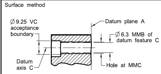
MMB_wfr3xa.jpg


ssss_pj6yz2.jpg


Here MMB for Datum feature C is Ø6.3 is this correct or

MMB of C = Ø6.3-0.25 = Ø6.05 ?
 
The 8x counterbore pattern is controlled with a position specification in which the datum reference frame is simply [C(M)]. In this case, the MMB of datum feature C is simply the MMC size (Ø6.3) because there are no datum references of higher precedence in the DRF, and there is no form tolerance on datum feature C.

If the specification invoked DRF [A|B(M)|C(M)], then the MMB would be Ø6.3 - Ø0.25 = Ø6.05.

EDIT: The 8x counterbore pattern is not controlled. Each counterbore is controlled individually to datum C, where datum feature C is the corresponding thru hole. There are 8 individual features representing datum C individually, not as a pattern. The Ø0.25 position specification applies to the pattern, which is not C, so the Ø0.25 would never be used to augment the MMB of datum feature C.
 
The MMB of datum feature [C] is only Ø6.05 when the feature that references it also references [A|B]. In the case of the counterbore geometric tolerance, there is no reference to [A|B]. Had there been a straightness tolerance on datum feature [C] that overrides the Envelope Principle control on datum feature [C], that would have been included.
 
Thanks Jacob Cheverie (Aerospace),

1.
Here only c[M] is given - ok.

2.
What could be if form tolerance is given?

Jacob, How you learn the Rules of these? by means of experience or there is any guidelines book?

 
ASHWA,

Refer to ASME Y14.5-2018 Para. 7.11.6. Also, please see the edit that I made to my last post. There is a subtle detail in the image.

If there were a form tolerance applied at MMC, MMB would be MMC size minus the form tolerance.
 
Thanks a lot Jacob Cheverie (Aerospace),

also Thanks to 3DDave (Aerospace),Burunduk (Mechanical).

Your presence are always valuable...!!
 
Kedu and All,

Back to the discussion of Fig. 4-21 from Y14.5-2009. It was mentioned a while back that ISO would allow the use of A(M)-B. Would that be better? Is it even definable? I'm actually not sure, because I've never thought through the details of how a multiple datum feature (now called a common datum feature in 2018) would work with mixed modifiers or mixed feature types. Here is what I would think:
-Feature A, being referenced at MMB, would need to be enveloped by its TGC
-Feature B, being referenced at RMB, would need maximum contact with its TGC
-Features A and B should have equal precedence, with neither taking precedence over the other

For the as-produced part with LMC-sized feature A in Fig. 4-21(c), A(M)-B appears to be straightforward. The part could sit on the gage exactly as shown, with clearance on A and full contact on B.

For the configuration with MMC-sized feature A in 4-21(d), to me A(M)-B is not as straightforward. Should the part sit on the gage exactly as ahown, with full 4-point contact on A and 1-point contact on B? It seems like A is being given higher precedence.

What if the reference was A-B? How should the part in 4-21(d) sit on the gage in that instance? We would try to get maximum contact on both A and B, without one taking precedence over the other. This should mean that there would be less than full 4-point contact on A, and more than 1-point contact on B. But if that were the case, then feature A is given less priority in A-B than it was in A(M)-B. In other words, applying the MMB modifier to the A reference gives it higher priority. At the very least, this goes against the usual "hierarchy" of constraint, where RMB is more restrictive and MMB is less restrictive.

It is also possible that if the multiple datum feature is comprised of both a planar feature and a feature of size, then equal precedence cannot be achieved. It may also depend on how the datum features are toleranced relative to each other. Fig. 4-21 has a perpendicularity on B w.r.t. A. Does that need to be taken into account for the A(M)-B reference? If the perpendicularity had been on A w.r.t B, then we would have taken that into account in the TGC size for A in the A(M)-B reference.

At the end of the day, I don't think that Y14.5's example-based definitions provide enough detail (i.e. rules) on precedence or datum feature / TGC contact for us to really know how an A(M)-B reference would work. I wonder how ISO defines it.


Evan Janeshewski

Axymetrix Quality Engineering Inc.
 
Hi Friends,

Is my Assumption correct?

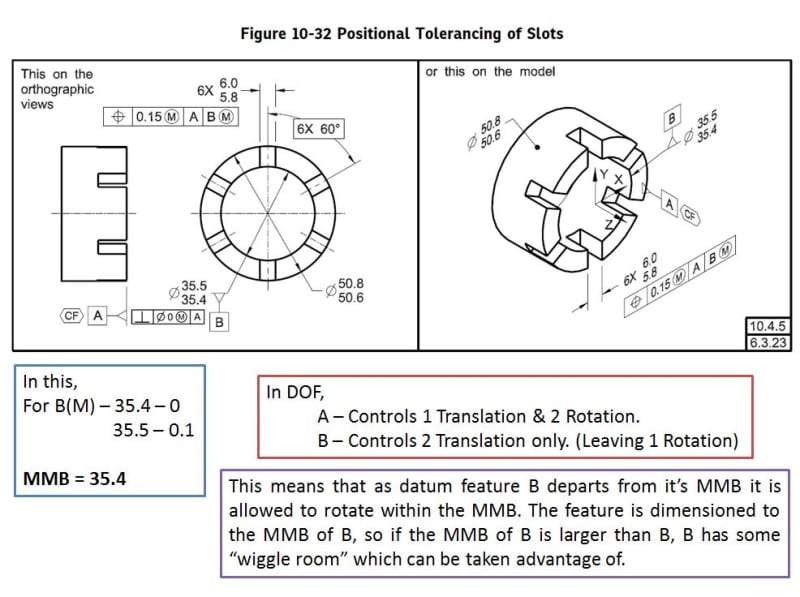
23012021_wzpjtu.jpg
 
Regarding the DOF constraints and the MMB calculation - you are correct.

As for the description in the bottom frame - there are some inaccuracies there. Here is a correction I propose:

Instead of:

"it is allowed to rotate within the MMB"
-It is allowed to translate as limited by the MMB.*

"The feature is dimensioned to the MMB of B"
-The feature is toleranced with reference to B at MMB.

"if the MMB of B is larger than B"
-If datum feature B is larger than its MMB.

*It is also allowed to rotate about the datum axis B but that has no relation to B being referenced at MMB or RMB.

If anything is unclear, draw a hard gage that includes datum feature B (at MMB) simulator, and the part engaged with it. Then you'll see how the movement of the part is constrained by this fixture.
 
Thanks Burunduk (Mechanical)...!!

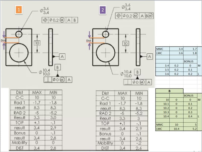
Have a doubt in the following DISTANCE calculation.

you_dt7yu7.jpg


Have the doubt in calculation of Bonus tolerance in MIN (LMC) column.

in Min for Bonus it is given -0.1

Why didn't consider the Bonus from Datum feature B?
(M) 10.0 Bonus is 0.0
10.1 Bonus is 0.1
10.2 Bonus is 0.2
10.3 Bonus is 0.3
(L) 10.4 Bonus is 0.4
So, for Min calc. In condition 1 & 2,
Bonus could be 0.1(3.6 - 0.2/2) + 0.2(10.4 - 0.4/2) = 0.3.
Is my assumption right?
 
Status
Not open for further replies.

Part and Inventory Search

Sponsor