Eng-Tips is the largest engineering community on the Internet

Intelligent Work Forums for Engineering Professionals

  • Congratulations waross on being selected by the Tek-Tips community for having the most helpful posts in the forums last week. Way to Go!

Understanding datum displacement

Status
Not open for further replies.

GCalin

Electrical
Feb 24, 2022
3
0
0
BR
Hi everyone,
I was checking a dwg and got confused with how a datum displacement should work a position tolerance:

Capture_hnxz4s.jpg


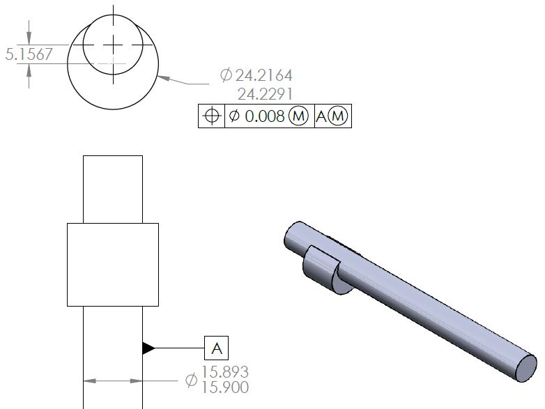
If I understood correctly the MMC modifier of the center position of the eccentric cylinder, it means it can vary within a circle of 0.008mm when the diameter is maximum (24.2291mm) and will be expanded to 0,0207mm when it is in its minimum allowed value (24.2164mm), correct?
How about the MMC modifier to the A datum? I could not understand how the datum displacement would apply in this case.

Thanks for your help,
 
Replies continue below

Recommended for you

In this specific case, the math works in the same way as the expanded tolerance you've already calculated: any deviation of the datum cylinder from its maximum size allows the effective alignment between the two to be greater.
In other words, If both diameters are at their largest (24.2291 and 15.900, then the allowable offset between the two is 0.004 (that's the position tolerance of diameter 0.008, which equates to 0.004 radial offset in any direction). But if both diameters are made at their smallest (24.2164 and 15.893), then the allowable offset between the two is 0.01385 (that's the position allowance effectively becoming 0.0277 diametrically speaking, or 0.01385 radially speaking).

Huge caveat: I began by saying "in this specific case" because most of the time when the "M" is placed after a datum, you cannot add its contribution into the given position tolerance as I have done -- that's because it doesn't really cause the position tolerance to grow, but it allows the position tolerance zone to shift around. (Subsequent commenters will certainly point this out, and I guess I shouldn't start you out learning about datum shift in the wrong way.) But since you have only one datum, and it acts in the same direction of space as the other feature, it's an easy way to get you thinking about datum features that are not made at the designated material boundary, and it's how the ASME standard explained it up until 2009.

Unrelated comment: When using high-low limit tolerancing, It's customary to place the larger number above the smaller number.
 
Thank you for the explanation. This is trickier than I thought.
In my (very limited) GD&T understanding, modifiers applied to datum would never bonus the associated tolerances, indicating only allowed shifts to accommodate the tolerance range. However using this idea, the specifications on the drawing would not make very much sense to exist.
 
...modifiers applied to datum would never bonus the associated tolerances, indicating only allowed shifts to accommodate the tolerance range.

That's correct. The modifier on the datum does provide some extra "fudge factor," but it's not additive to the position tolerance. It does contribute to the measured location between the two diameters, which is where my math came in. That's because the true datum is the axis of the small diameter as if it were at its maximum size. Since that actual size of the small diameter can be less than that, it creates a discrepancy (often called datum shift) between the actual axis of the small diameter and the datum axis derived from that same feature. Result: Although datum shift is not additive into the position tolerance number, in this case the datum shift is additive to the displacement between the two diameters as they actually are.

For some applications it does make very good sense. Think of the part you've shown as simply dropping loosely into a part with the reverse features, such as a through-hole with a counterbore around it (well, an off-center counterbore). The male part with maximum diameters would not allow for much axial offset. But the male part with one or both diameters at the smallest could have greater axial offset and still fit with the female part.

So like anything else in GD&T, it comes down to function. Depending on what your given part is meant for and how it fits, then we could decide if the position tolerance warrants one or both "M" modifiers.

(FYI, edited a couple of times for wording/clarity.)
 
GCalin,

I agree with Belanger's explanation.

Do you have access to a copy of the ASME Y14.5 standard? If so, which revision? There is a figure near the end of the Position section that is very similar to the situation in your example. It shows the effect of the (M)'s in terms of a hard gage, which is a good way to visualize the requirement.

In the case of your part, the gage would have two cylindrical sleeves offset by 5.1567. One sleeve (for the A pin) would have a diameter of 15.9000 and the other sleeve would have a diameter of 24.2371. The part needs to fit in both sleeves at the same time.

The effect of the (M) on the datum feature reference is that pin A doesn't necessarily center itself in the gage sleeve - there is generally clearance, unless the as-produced size of feature A is right at MMC.

Evan Janeshewski

Axymetrix Quality Engineering Inc.
 
A interesting way to visualize the tolerances ranges with the sleeve gage example. Thank you for pointing this out Axym.
I have to get a full copy of the ASME Y14.5 std. Most my references are bits and pieces from different sources.
 
Status
Not open for further replies.
Back
Top