Continue to Site

Eng-Tips is the largest engineering community on the Internet

Intelligent Work Forums for Engineering Professionals

  • Congratulations pierreick on being selected by the Eng-Tips community for having the most helpful posts in the forums last week. Way to Go!

Unilateral Profile Tolerance with Bonus 6

Status
Not open for further replies.

DRWCA

Mechanical
May 14, 2020
2
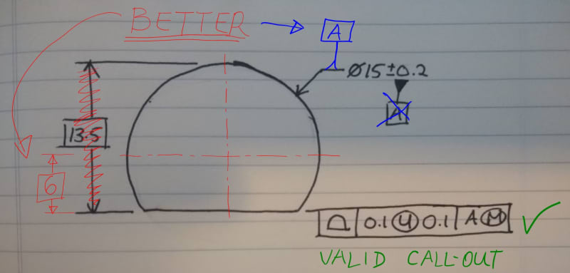
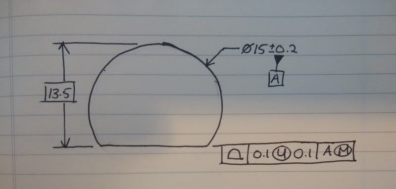
Curious about the interpretation of the unilateral tolerance zone in the following example. As A departs from MMC, does the bonus tolerance applied to the profile control now allow for removal of material, or is the implied 'outside only' condition preserved, ie. would the implied profile callout at a diameter of 14.8 be |0.5 U 0.1| or |0.5 U 0.5|?

Or perhaps the better question - is this even a valid callout?

oT7QBAGQ_ejtr8q.jpg
 
Replies continue below

Recommended for you

Datum feature A establishes an axis - wouldn't the basic dimension be drawn from the center of A? Well, technically, from the center of the true geometric counterpart of A at 15.2?
 
Good point. I guess the question about bonus tolerance still applies though.
 
Since the feature is not located to datum feature A it's not a valid call out.

Had the dimension been to the datum feature axis it would work as imagined by creating a gage that has a partial 15.2 diameter boundary with a scribe line that is some value, whatever it is supposed to be, from the center of the diameter to where the flat is and another that is 0.1 farther than that. Drop the part in the gage and as long as it can be manipulated so the flat lies between the two lines and is not smaller than 14.8 diameter, it passes.
 
If the basic was drawn from the center of datum feature A, then what the callout is establishing is a planar tolerance zone of width 0.1 starting at the noted basic dimension and extending outward. The MMB modifier on datum feature A should do nothing to modify your tolerance value internally or externally. The only purpose of the modifier would be for some added mobility when A departs from MMC size.

For example, let's assume the planar surface is meant to be 13.5 BASIC from the center of A. Let's assume that it measures at 13.7 - it's too far away. As datum feature A departs from MMC, it can translate/rotate within it's true geometric counterpart (of MMC size) until the planar surface is located back in the tolerance zone described above.
 
Side note - profile tolerances are always applied RFS. The (M) in conjunction with the datum feature callout is a Material Boundary Modifier which denotes Maximum Material Boundary (MMB) for datum feature A. This allows datum feature shift (the behavior that Jacob described), and is NOT a bonus tolerance - though it might look like one in some cases.
 
It is a valid call-out as is. The profile call-out is controlling the position wrt A, orientation (parallelism) wrt A, and form (flatness) of that flat surface.

There is no bonus tolerance. The (M) after A indicates MMB (datum shift), which would allow the inspector to shift (translate and/or rotate/tilt) the part in order to bring it in spec., if possible (depending on the measured size of datum feature A). The fixed size of the datum A simulator (gage) would be 15.2. For example, if the part was made at dia 15, then you would have 15.2 - 15 = 0.2 (0.1 mm radially) play.

Better_rpcnim.jpg
 
The profile callout itself is valid but, as mentioned by others, the basic dimension is defined incorrectly. See fig. 4-30 in Y14.5-2009 or figs. 7-32 and 7-33 in Y14.5-2018.
 
Tarator,

Basic 6 is not just better over 13.5. Basic 13.5 is simply incorrect.
 
pmarc,

I do not agree. The theoretically perfect part would be dia 15. Basic dimensions can be translated. Parts do not have to be dimensioned from datums.

13.5 basic dimension is simply showing where the flat surface would lie in a perfect part. Whether it is from the edge of the circle or the center of the circle should not matter.
 
Tarator,

This video from Tec-Ease is somehow related with discussed topic.
So far, I am with pmarc.

Sorry, but after you review the video below maybe you can change your mind or bring more arguments (read paragraphs and verses from the standard) to your above statements.

 
Tarator,

Parts are dimensioned from the DRF. The basic dimension is a theoretically perfect dimension and it certainly shouldn't depend upon the size of the datum feature. If it is drawn from the edge of the datum feature, it is directly effected by the size. As the datum feature A gets smaller, what happens to that basic dimension? Does it stay the same? Does it get smaller? What does that mean for the toleranced surface?

The idea is that the surface isn't dimensioned to the datum feature, but rather the MMB of the datum feature. The MMB will be "perfect" so if you wanted to add the radius of the simulator to your measurement and measure it as such, I assume that you can. As far as the drawing is concerned, however, I believe your basic should come from the center of A to avoid any ambiguity as I mentioned above.
 
Tarator said:
I do not agree. The theoretically perfect part would be dia 15. Basic dimensions can be translated. Parts do not have to be dimensioned from datums.

13.5 basic dimension is simply showing where the flat surface would lie in a perfect part. Whether it is from the edge of the circle or the center of the circle should not matter.

Unfortunately it does matter. As is, the profile callout basically defines a tolerance zone relative to a datum derived from datum feature A simulated at MMB. Therefore, there needs to be a basic distance between the datum and the tolerance zone/true profile, otherwise the entire specification is incorrect. There would be no issue if the diameter of datum feature A was basic, but that is not the case as we all can see.
 
greenimi,

In the video from Tec-Tease, the size dimension does not have a nominal value!

Drawings/3D models are perfect and have no variations. Actual physical parts have variations. You may choose not to show any basic dimensions at all if you specify that the 3D model is nominal/theoretical match data in your drawing. And the person who received the drawing or 3D model with PMI/MBD can measure from where they want once they open up their software.


Jacob Cheverie,

Parts do not have to be dimensioned from the DRF. Please refer to these two videos:
1) 2)
 
Tarator,
Basic dimensions for location of features are given either from the DRF or from a "true profile".

What is the true profile of a directly toleranced diameter?
Suppose that the 15+/-0.2 diameter was represented as 14.8+0.4/0. Would you then say that the 13.5 basic dimension is given from the theoretical 14.8 diameter - according to the nominal dimension, or from the 15 diameter - according to the middle of tolerance size? Also, what would be your answer if the dimension representation changed to 14.8-15.2?
When you answer these questions, if you have access to any version of the ASME Y14.5 standard, please provide the evidence from the standard to support your answers.
 
Tarator said:
In the video from Tec-Tease, the size dimension does not have a nominal value!

Tarator,

I have to repeat after pmarc: "Unfortunately it does matter"
Nominal dimension has nothing to do with the entire concept presented in Tec-Ease's video.(i.e. does not matter if Ø40.01-40.11 is shown as is in Tec-Ease's video or shown as Ø40.06±0.05, the concept is still there). Why the entire Tec-Ease's concept should change if their ID is changed to Ø40.06±0.05?

After you answer maybe Burunduk's related questions, maybe you can convince yourself you are just plain wrong! If not, I am sorry for you.....

Again I repeat, from pmarc's previous post "There would be no issue if the diameter of datum feature A was basic, but that is not the case..."

When 4 people are telling: you are incorrect and you still debate...I don't know what else to say.
There is a Central American saying that goes along the line of "If one person tells you you're drunk, and you feel fine, ignore him. If ten people tell you you're drunk, go and have a lie down".
 
In the video from Tec-Tease, the size dimension does not have a nominal value!

A nominal value, whether stated or implied, does NOT** dictate "theoretically perfect geometry" in the same way that a basic dimension does.

Basic dimensions and directly toleranced dimensions are fundamentally different. Its pretty clear by looking at the definitions that these concepts are not equivalent.

Y14.5-2018 said:
3.27 DIMENSION, DIRECTLY TOLERANCED
dimension, directly toleranced: a dimension with an associated plus/minus tolerance or limit dimension values.

Y14.5-2009 said:
1.3.56 Size, Nominal
size, nominal: the designation used for purposes of general identification.

Note it says general identification! Not theoretically exact or even approaching such, as opposed to:

Y14.5-2009 said:
1.3.23 Dimension, Basic
dimension, basic: a theoretically exact dimension.

**EDIT
 
Just realized my post had a pretty critical typo - I have edited to read that "A nominal value, whether stated or implied, does NOT** dictate 'theoretically perfect geometry' ". Apologies!
 
greenimi,

I once had 5-6 people saying that flatness controls coplanarity (on multiple planar features). I said it does not. I guess I was wrong because min. 5 people said otherwise. Maybe you also think whoever yells louder is right. Or maybe you were drunk when you were typing? You can use that as an excuse to save yourself.

So I will ignore greenimi and go back to the original sketch/drawing, maybe this time from a different view of angle:

Imagine you have the 3D model opened up in your CAD package. And all you see is a size dimension with tolerances (dia 15 ± 0.2), no basic dimensions at all. And you like to know the distance between the planar feature and the center of the cylinder. You use the measurement tool in your software and measure the distance from the planar face to the edge of the cylinder as 13.5 (in this scenario, it is more convenient). Then you would calculate 13.5 - 15/2 = 6. Would that be wrong? Why can't you do it in a 2D drawing? If there was no nominal value, then, of course, you wouldn't be able to do that.

All I am saying is that it is not the ideal way to dimension that feature from the edge of the cylinder. I would do it from the center. But in my opinion, it is not incorrect to dimension it from the edge.


Status
Not open for further replies.

Part and Inventory Search

Sponsor