Continue to Site

Eng-Tips is the largest engineering community on the Internet

Intelligent Work Forums for Engineering Professionals

  • Congratulations pierreick on being selected by the Eng-Tips community for having the most helpful posts in the forums last week. Way to Go!

Unilateral Profile Tolerance with Bonus 6

Status
Not open for further replies.

DRWCA

Mechanical
May 14, 2020
2
Curious about the interpretation of the unilateral tolerance zone in the following example. As A departs from MMC, does the bonus tolerance applied to the profile control now allow for removal of material, or is the implied 'outside only' condition preserved, ie. would the implied profile callout at a diameter of 14.8 be |0.5 U 0.1| or |0.5 U 0.5|?

Or perhaps the better question - is this even a valid callout?

oT7QBAGQ_ejtr8q.jpg
 
Replies continue below

Recommended for you

Tarator,

So all these 5-6 people are wrong and only you are right IN THIS CASE?
(Just because "your 5-6 people" were wrong on the flatness/ coplanarity and only YOU were right, that does not mean MY "5-6 people" are wrong and again only you are right/correct).


Please read what chez311 stated, specially the definition posted.
Mixing up those definitions for convenience does not make YOU right.

Tarator said:
And all you see is a size dimension with tolerances (dia 15 ± 0.2), no basic dimensions at all. And you like to know the distance between the planar feature and the center of the cylinder. You use the measurement tool in your software and measure the distance from the planar face to the edge of the cylinder as 13.5 (in this scenario, it is more convenient). Then you would calculate 13.5 - 15/2 = 6. Would that be wrong?


Tarator,
Looks like YOU have a perpetual issue with nominal dimensions. In the thread below another GDT expert (J-P Belanger) on this forum, explained you the same thing about the nominal dimensions.
You still don't realize how incorrect you are after all of those years. Sad, sad! I guess is hard to kickoff the old habits.
 
Tarator,
You seem to trust the Tec-Ease videos. Notice how in the first video you posted, even where features are located from the edge of the part, their location is always linked and can be traced back to the datum features by a chain of basic dimensions. This is not the case in the OP. As you were told a few times already - it could be similar if the 15 diameter was basic, then you could conclude that there is an implied basic 7.5 radius that connects the axis with the edge of the cylinder and the math of 13.5-7.5=6 would be useful to determine the location of that bottom face relative to the origin of measurement. As for your second video, I don't think it is even relevant to what is being discussed. Also, notice how in the Tec-Ease video greenimi linked to, the tip is "do not mix basic and directly toleranced dimensions",
not "do not mix basic and directly toleranced dimensions without a nominal value".
 
Tarator,

I think the reason so many people think they know GD&T (and YES, I am talking about your case) --who really don't--is because so many OTHER people don't know it.

They say if you want to feel thin you should hang out with fat people.

So, I guess simply being around other people (Your 5-6 people/ flatness versus coplanarity)
Tarator said:
I once had 5-6 people saying that flatness controls coplanarity (on multiple planar features). I said it does not.
who don't know enough to challenge GD&T specifications then we delude the unconsciously incompetent into believing they're competent.


I think the original question of the OP (about the effect of MMB on the unilateral tolerance) got overlooked in the argument over dimensioning. Had the 13.5 basic been replaced by basic 6 from datum axis A, a feature produced with the flat offset less than 6 from the axis of datum feature A could indeed be approved due to datum shift.
 
Burunduk,

Sometimes (maybe more often than that), the standard is not very clear, which also depends on the version. So we find ourselves "extending" or "interpreting" some statements in the standard. My view of the OP's sketch was that it is not as concrete as black and white, or 2+2=4, to declare it as incorrect without solid proof or evidence from the standard, but rather a personal opinion or interpretation, or by simply counting who said what.


Hi All,

I agree that the correct answer shouldn't be determined by how many people have said it, or who they are. If Tec-Ease or pmarc or myself gives an opinion about a GD&T topic, that doesn't mean that it's absolutely correct. It just means that it's most likely correct ;^).

Here are other cases to consider, that may shed some light on the situation. What basic dimension (for the distance between the OD extremity and the flat) would be valid if:

1. the OD had been modeled at 15.2 and toleranced with the equal bilateral tolerance of 15.0 +/- 0.2?

2. the OD had been modeled at 15.2 and toleranced with a unilateral size tolerance of 15.2 -0.4 +0 ?

3. the OD had been modeled at 15.5 and toleranced with a minus-minus size tolerance of 15.5 -0.7 -0.3 ?

4. the OD had been modeled at 15.1 and toleranced with a limit tolerance of 14.8 - 15.2 ?

5. the OD had been modeled at 15.0 and toleranced with a datumless profile tolerance of 0.4?

6. the OD had been modeled at 15.2 and toleranced with a datumless profile tolerance of 0.4?

I'm interested to hear how everyone would answer these.

Evan Janeshewski

Axymetrix Quality Engineering Inc.
 
Evan,
The way you posed the question, none of them would be valid because the root of your question still keeps the basic dimension "between the OD extremity and the flat."
Since your question merely changed how the OD size is given, but hasn't changed the way datum feature A is labeled, then the basic dim shall still come from the center of the OD, not its 12 o'clock extremity.

John-Paul Belanger
Certified Sr. GD&T Professional
Geometric Learning Systems
 
Tarator,
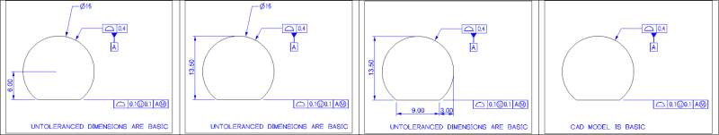
There are places where the standard is unclear and can be subject to more than one interpretation and extensions, and there are places where the standard is crystal clear and there should be no personal interpretations. Otherwise, we don't need the standard and everyone is free to put on their drawings whatever they want and then engage in endless debates and arguments over what drawings mean. I tried to encourage you to investigate and find out yourself that the Y14.5 standard clearly specifies that a true profile of a feature is defined either by basic dimensions or by the CAD model (where there is an appropriate note on the drawing and no other specification):

"A true profile is a profile defined by basic radii, basic angular dimensions, basic coordinate dimensions, basic size
dimensions, undimensioned drawings, formulas, or mathematical data, including design models."
- para. 8.2 in the 2009 version.

Note that nominal values of +/- dimensions are not part of it.

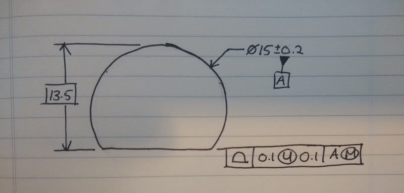
If you don't care about what the standard has to say think of the person who will put the 13.5 basic from the edge of the cylinder on his drawing with the 15+/-0.2 diameter datum feature, thinking it means the same thing as 6 basic from the datum axis, and eventually will end up arguing with a vendor that will be saying that parts that were produced out of tolerance when checked to the DRF are in spec, and as proof will be showing how he measures the distance from the edge of the cylinder to the flat, getting the right numbers.
 
The OP's question was clearly about how to read and interpret the DRAWING. If someone wants to blur the lines and mix some terms from model based definition that is another story (how to model the part, which is the nominal dimension on the model--perfect part modeled, what and how to measure the model, etc.) ASME Y14.41 (Digital Product Definition Data Practices) might have some good suggestions, however not complete and maybe should be supplemented with some company's internal standards on modelling. But again, that was NOT part of the OP's question, as far as I am concern.

axym said:
I agree that the correct answer shouldn't be determined by how many people have said it, or who they are. If Tec-Ease or pmarc or myself gives an opinion about a GD&T topic, that doesn't mean that it's absolutely correct. It just means that it's most likely correct ;^).

Evan,
I agree with you here about credentials. But that does not help to maintain a constructive discussion.
Somewhere you have to draw the line. Otherwise everything is relative and he can have a philosophical discussion from that point, not an (educated) engineering drawing interpretation.
Tarator did not provide anything from the standard to support his stance, just opinion based on his level of education. Which granted, could be extremely high, but so far contradict flagrantly other (equally educated and knowledgeable) subject matter experts on this forum.


Evan,

Regarding the technical stuff
axym said:
What basic dimension (for the distance between the OD extremity and the flat) would be valid if:

1. the OD had been modeled at 15.2 and toleranced with the equal bilateral tolerance of 15.0 +/- 0.2?

2. the OD had been modeled at 15.2 and toleranced with a unilateral size tolerance of 15.2 -0.4 +0 ?

3. the OD had been modeled at 15.5 and toleranced with a minus-minus size tolerance of 15.5 -0.7 -0.3 ?

4. the OD had been modeled at 15.1 and toleranced with a limit tolerance of 14.8 - 15.2 ?

5. the OD had been modeled at 15.0 and toleranced with a datumless profile tolerance of 0.4?

6. the OD had been modeled at 15.2 and toleranced with a datumless profile tolerance of 0.4?

I agree with J-P, the way you asked the question (what basic dimension would be valid...?) 1, 2, 3 and 4: none.
On 5 and 6 I would like more details, datumless profile applied to the OD? and then would you remove the ± (15±0.2)?


greenimi,

Sorry, I wasn't clear about the datumless profile. That was meant as a replacement - the directly toleranced 15 +/- 0.2 size dimension would be removed.

J-P,

I was thinking that there might be another way that we could show that if the OD was controlled with a directly toleranced size dimension, then a basic dimension between the extremity and the flat would not be valid. I was also thinking that if the OD was controlled with datumless profile instead of a directly toleranced dimension, then that would change things.

Evan Janeshewski

Axymetrix Quality Engineering Inc.
 
Evan -- so you're not trying to show any way that the basic dim given in the OP could be valid. You're trying to redimension the OD in a way to clarify why the basic dim given in the OP is never valid?

Honestly, I think you're overcomplicating it. It boils down to this: As long as the datum feature symbol stays where it is, that means that the datum is the axis, and thus, the basic dim must originate from the axis (para. 11.6.1.1, "The toleranced feature is located from specified datums by basic dimensions" -- they say this regarding composite profile, but it applies to regular profile as well).

John-Paul Belanger
Certified Sr. GD&T Professional
Geometric Learning Systems
 
Interesting discussion. One of the issues never mentioned is, in my opinion the following:

Tarator said:
Imagine you have the 3D model opened up in your CAD package. And all you see is a size dimension with tolerances (dia 15 ± 0.2), no basic dimensions at all. And you like to know the distance between the planar feature and the center of the cylinder. You use the measurement tool in your software and measure the distance from the planar face to the edge of the cylinder as 13.5 (in this scenario, it is more convenient). Then you would calculate 13.5 - 15/2 = 6. Would that be wrong? Why can't you do it in a 2D drawing? If there was no nominal value, then, of course, you wouldn't be able to do that.

CAD measurements are taken from the model UOS (unless otherwise specified), but in this case the culprit dimensions are specified. So, I see no good reason to measure those dimensions from the CAD (15±0.2). UOS note is added on the model or on the drawing for the purpose mentioned by Tarator, but using them with wrong intention does not help anyone.
 
axym said:
greenimi,

Sorry, I wasn't clear about the datumless profile. That was meant as a replacement - the directly toleranced 15 +/- 0.2 size dimension would be removed.

axym said:
I was also thinking that if the OD was controlled with datumless profile instead of a directly toleranced dimension, then that would change things.

Definitely it would, as mentioned few days ago by pmarc
pmarc said:
pmarc (Mechanical)
3 Jun 20 18:58
There would be no issue if the diameter of datum feature A was basic,

Looks like no matter how we are spinning it the current specification is plain wrong.
 
I think the last couple of posts mesh on the same idea, and so then I would agree -- thanks for clarifying.
If the OD is basic, then we would have the basic dim that I was lobbying for because it would be a chain of basic dims from from the axis (a radius), but by way of the basic OD.

John-Paul Belanger
Certified Sr. GD&T Professional
Geometric Learning Systems
 
J-P,

Yes, I'm trying to objectively show that if the OD has a directly toleranced size dimension then the basic dimension is never valid. Sorry it got so complicated.

If the OD has the datumless profile instead of the directly toleranced size dimension, then I would say that any basic dimensioning scheme is valid and equivalent:

DiscWithFlat_yyyvwa.png


We don't necessarily have the basic dimension that you are lobbying for. Would you agree?

Evan Janeshewski

Axymetrix Quality Engineering Inc.
 
We do have the basic I was lobbying for. Though not directly labeled, it's a chain of basics: from the profiled flat surface back to the 12 o'clock tangent point of 13.5 mm, and then an implied basic of 7.5 mm.
Thanks for adding the pics.
(An aside: That 3rd drawing is an interesting way to give the diameter of the part!)

John-Paul Belanger
Certified Sr. GD&T Professional
Geometric Learning Systems
 
J-P,

The way I look at it, the presence or absence of an explicit basic dimension makes no difference to the meaning of the specification (if a CAD model is referenced). In other words, the basic dimensions are all there in the CAD whether they are explicitly annotated or not. If a directly toleranced dimension is specified, then that changes things - the feature is no longer theoretically exact. I agree with the opinion that mixing directly toleranced dimensions and profile tolerancing is problematic. I know that Y14.5 has examples that do this, but I wish that these would be eliminated.

So I guess that the question about the validity of the basic dimension comes down to this:


I believe this is how Y14.5 currently works.

Evan Janeshewski

Axymetrix Quality Engineering Inc.
 
Evan and all,

Why the profile is not 0.2 in the VALID (green) scheme?
NOT VALID: 15±0.2 = 14.8 - 15.2
VALID: profile within 0.4:
15.0-0.2-0.2 = 14.6
15+0.2+0.2 = 15.4

Thank you Evan


Status
Not open for further replies.

Part and Inventory Search

Sponsor