Continue to Site

Eng-Tips is the largest engineering community on the Internet

Intelligent Work Forums for Engineering Professionals

  • Congratulations cowski on being selected by the Eng-Tips community for having the most helpful posts in the forums last week. Way to Go!

use of centerline for pattern of features…

Status
Not open for further replies.

Tenkan

Mechanical
Jan 27, 2012
93
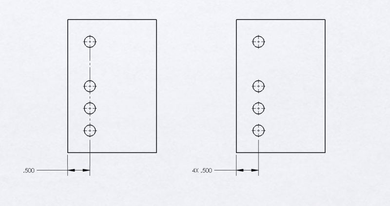
What does the centerline mean when used to show a pattern of features?

Does it mean only to indicate all the features individually within the pattern or does/can it mean an average location of the features in aggregate?

Attached is a drawing example for this question... to me, both examples shown mean the same thing am I wrong?
CENTERLINE_USE_h2xgtg.jpg


lightweight, cheap, strong... pick 2
 
Replies continue below

Recommended for you

Centerline by itself doesn't mean anything.

Also, if you are in compliance with ASME Y14.5, "pattern" means "two or more features or features of size to which a locational geometric tolerance is applied ..." etc.

Since you don't use geometric tolerances, neither of your pictures represents a "pattern"


"For every expert there is an equal and opposite expert"
Arthur C. Clarke Profiles of the future

 
The first example shows that the .500 dimension applies to all 4 features as they share a common centerline. The second accomplishes the same thing by the use of 4X .500.

----------------------------------------

The Help for this program was created in Windows Help format, which depends on a feature that isn't included in this version of Windows.
 
I am new here and I would like to ask what means:
"4 features as they share a common centerline".
What is a common centerline?
And how you determine that?

Thank you
 
Checkerhater, I had to think about this one for a minute but your right, the only thing that establishes a pattern is a geometric tolerance.

So without the use of a geometric tolerance, the centerline only means the .500 dimension applies to all 4 features independently, the same thing as “4X .500”

Gabimot, the common centerline is determined visually by the features lining up with only one centerline, if any of the features sharing a centerline are not in fact on that line even by a micron it is the drafters responsibility to indicate that with another dimension.


lightweight, cheap, strong... pick 2
 
Wooo
" the common centerline is determined visually by the features lining up with only one centerline, if any of the features sharing a centerline are not in fact on that line even by a micron it is the drafters responsibility to indicate that with another dimension"

I just learn something new: centerline is determined visually..............

And also I learn to transfer the responsibilities from the engineers to the drafters.......In other words if an engineer is incompetent and does not how to dimension the drawing, it is the drafter responsibility.
 
greenimi, please correct me if Im wrong Im willing to learn here too. How would you answer gabimots questions?

lightweight, cheap, strong... pick 2
 
I would just explain it to him/her how would YOU read the drawing attached. Being sarcastic does not solve anything (like did not solve or answer the question when I replied, right)
I still think gabimot’s question is legitimate. Can you find the common centerline definition is the standard?
There are examples of features being coaxial such as A-B datum feature compound.

 
Greenimi, My apologies if I came across sarcastic, wasn’t my intention. But I did answer gabimot’s question as how I read the drawing. I have a copy of Y14.5-2009 but not Y14.2… which IIRC covers the use of lines like centerlines, maybe I missed it but I couldn’t find anything in 14.5. So you are right I cant find anywhere where a common centerline is the standard, in fact that is why this question came up at work and why I posted this here to find out if their was a standard. As far as I know they are mostly asthetic but Ive always thought that the dimension to the centerline applies to all features shown on the centerline since they are not otherwise specified... which in a practical use can only be determined visually.

lightweight, cheap, strong... pick 2
 
The bigger question to ask is why you need the tolerance ON the dimension? Probably you will say because we cannot make it perfectly located, right?
So, I will ask what you cannot make it perfect? The dimension or the feature?

 
And to directly answer your question ( and hopefully you will answer my questions from my previous post), in my opinion, the holes could be the size tolerance apart from each other plus some additional measurement errors and uncertenties due to the fact you are not measuring (or required to measure) the holes from the same physical location. And since the left surface will not be perfect hence not the same origin of measurement.
Just showing 4x .500 is just a drafting practice but does not imply the measurements must be taken from the same point.
Anybody else agree or disagree with my statements?

 
gabimot said:
I am new here and I would like to ask what means:
"4 features as they share a common centerline".
What is a common centerline?
And how you determine that?

Centreline is an unfortunate term here. It is obviously not a centreline. It is a dimension line. On SolidWorks, I systematically dimension to the furthest hole. I can then inspect along the dimension line and verify that the holes indeed all are on the line. Sometimes, they aren't.[smile]

I only do the 4X[ ].500 on a complicated drawing when the long dimension line adds excessively to the mess. Sometimes, it is safer to dimension some of the holes separately.

--
JHG
 
Koda94 said:
...

So without the use of a geometric tolerance, the centerline only means the .500 dimension applies to all 4 features independently, the same thing as “4X .500”

If you go 4X[ ].500 on your drawing, I would assume that everything on the dimension line is located to whatever default tolerances are called up on your title block. Your example is harmless because it is a pattern, officially or otherwise. The holes all are the same size and probably need to be located to the same tolerance. Perhaps 4X[ ].500[±].010.

Things get messy when you have more than one type of hole on your dimension line, each of which requires a different locating tolerance. The nice thing about GD&T is that it places the positional tolerance on the hole specification, where it belongs.

--
JHG
 
It is obviously not a centreline. It is a dimension line.

I think this is being made more complicated than it actually is.
As shown in the example, it is indeed a centerline. A dimension line has no breaks.
It defines the vertical plane coincident with the hole(s) axis.
Tolerance-wise, there is no difference between a common centerline versus specifying the number of occurances and is often used to "simplify" a drawing, making it easier to interpret (especially if there a many holes which may cause confusion as to which dimension applies to which hole).

"Know the rules well, so you can break them effectively."
-Dalai Lama XIV
 
Quote: "It defines the vertical plane coincident with the hole(s) axis."


Could you, PLEASE, be more explicit of this approach. Is it a perfect plane? is it an imperfect plane? How you determine that plane?
Also, could you indicate the support from the standard for your approach?
 
Forget I mentioned plane.
A common centerline is only a convenience to define multiple instances of a dimension when taken from a common starting point (edge, feature, face, whatever).
It is the same as separate centerlines having one locating dimension with the number of occurances included. The same tolerances would be involved.
If you need some holes located to a tighter tolerance, either dimension them separately or use GD&T.
AFAIK the standards don't cover this specifically, but do use this method in examples. The standards don't cover much of what is basic drafting.

"Know the rules well, so you can break them effectively."
-Dalai Lama XIV
 
Status
Not open for further replies.

Part and Inventory Search

Sponsor