Continue to Site

Eng-Tips is the largest engineering community on the Internet

Intelligent Work Forums for Engineering Professionals

  • Congratulations KootK on being selected by the Eng-Tips community for having the most helpful posts in the forums last week. Way to Go!

User Defined Wind Loads & Diaphragms

Status
Not open for further replies.

Trenno

Structural
Feb 5, 2014
831
Hi everyone,

I’ve searched high and low for an explanation, but can’t find anything on google or the CSI docs. I have a few questions regarding User Defined Wind Loads and diaphragms (manual tabular input of Fx, Fy & Mz at a coordinate at each level).

How does ETABS distribute User Defined Wind Loads around the semi-rigid diaphragm?

How does ETABS choose what joints to apply the components of the diaphragm forces?

How are the “Reactive Forces” calculated?

For example, shown below is the user defined wind point load (including torsion moment) for a particular level applied at the centre of rotation (COR). Red is the slab outline and blue are the cores.
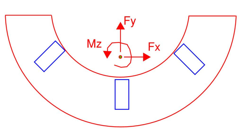
example_psxeit.jpg


example2_fqvjmr.jpg


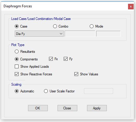
After running the model (which has no major errors), the user can display the diaphragm forces as either the Applied Loads or the Reactive Forces.

Is ETABS smart enough to distribute the point load around the joints of the diaphragm, even if the position of the point load isn't on the diaphragm? From what I understand, ETABS internally creates a special joint that is used for the application of this point load.
 
Replies continue below

Recommended for you

My understanding is that it lumps the single load on the centroid, so basically it's incompatible with a semi-rigid diaphragm. I've seen many a people who come unstuck on this point during peer reviews, all the load goes to the closest vertical structure, but they don't pickup on it.

You are better modeling the wind by applying a horizontal line or area load to the diaphragm as this better captures how it's applied in reality (spread across the width of the building).
 
If you're specifying the coordinate at which the load is applied, are you saying it still dumps it on the 'centroid'?

Agree with your second approach, I could take the Fy, Fx and Mz and turn it into equivalent line loads about the COR.

I'm surprised the CSI docs don't touch on this more, given how common it is to enter loads this way.

 
Sorry, it will dump it where you say. From memory, if you have a rigid diaphragm there's an option to apply it at the center of mass for seismic which is what I had in my mind.

I believe if you use the auto wind or seismic loads then it smears the load over a semi rigid diaphragm joints.

Who knows with CSI, big black box!
 
Yeah this whole smearing thing is what I'd like to know more about - but with manually input loads.

Might have to make some simple U-shaped building models and see where these forces are being dumped...

 
Well some of these have been mentioned above
1) This should not be done with semi rigid diaphragm as is completely unrealistic assumption, the load will be lumped at the closest node in the floor, a lumped concentrated load only makes sense with rigid diaphragms, for a semi rigid, you should distribute the load . This is what ETABS does when using auto wind loads with semi-rigid diaphragms


2) Lumps it to the nearest node from the point you have specified

3) Just as the reaction at those nodes from floor to walls/column, again this may not make any sense for a semi-rigid diaphragm with a user load.


Update:

After speaking with colleagues and CSI directly, ETABS doesn't distribute/smear user defined wind loads as described in the original post. It does however having a smearing algorithm for auto-generated lateral loads, it picks 10 joints of the pre-analysis mesh (ie corners of slab, wall ends, columns) that it applies forces to in order to replicate the resultant horizontal forces and torsional moments.

I think it would be a very handy future feature, to distribute user wind loads to a semi-rigid diaphragm in a similar manner that it does for auto-generated loads. Any project with a wind tunnel report will provide loads in a Fx, Fy & Mz format.

Further Info

EDIT: Sorry, I didn't see your post, Enrique. I agree with you though.

 
Agent666,

I've been developing an alternate approach which involves modelling a wind frame at each level that is external to the building envelope. This wind frame has a trapezoidal load on it to get the equivalent Fy and Mz.

At present, I'm using Link objects to deliver the reaction force from the wind beam to the slab diaphragms. This method, as expected with a semi-rigid diaphragm, results in a much more accurate load distribution compared to the user defined wind load method in the original post.

However, I'm always cautious using Link objects as sometimes they can skew the results if not defined properly. For this situation, I have very high stiffness for U1, U2 & U3 but have no stiffness for R1, R2 & R3. I've restrained each joint of the wind frame in the Uz direction and stopped it from rotating about the frame's longitudinal axis at one end.

The axial load in the links look reasonable and the diaphragm forces also. However, it's throwing some errors (loss of accuracy) of 6-8 digits, which I understand can potentially be somewhat ignored if the results are reasonable. This would suggest the wind frame and link object method isn't being implemented properly. Any thoughts?

The reason I'm not applying load directly to the slab edge or edge frame is because the real project has a complicated stepped facade and utilising a continuous wind frame makes it much easier to apply the trapezoidal load.

1111_yz50dq.jpg
 
Looks like an appropriate solution. To get some more info on the errors and possible locations of any instabilities, try running the analysis using the standard solver as this gives more information on exact locations that might be causing issues (also review the log to make sure its not ill conditioned due to a global instability). You also need to restrain the wind frame in the Ux direction if you have not already which may account for the loss of accuracy.
 
Thanks Agent, de-bugging ETABS models can be a fine art sometimes.

I've been trying to research appropriate stiffness modifiers (in-plane axial and shear) for thin metal deck slabs and ULS winds but haven't found a whole lot of references. Would be keen to hear your thoughts on this?

 
My own experience is that most people in New Zealand model only the topping thickness above the deck profile. The usual assumption is that this remains uncracked as in seismic regions our diaphragms need to essentially remain elastic according to our codes.

I've seen some people bound a stiffness value with a few model variations (like 0.5E-1.2E) to understand how the in-plane stiffness affects the distribution of forces to the lateral system and whether or not there is any sensitivity to this.

One reference that has some limited info is the NHERP guides here (in particular #3/5/13 about diaphragms).
 
Hi..
I presume all that was asked about has been answered. But still I shall put in my view
As far as I know, for rigid diaphragms:
(1) The central node of the diaphragm is located at its centre of mass, where the seismic loads are applied.
(2) Wind load in each direction is to be applied along the geometric centre of the projected length of the diaphragm, projected in that direction. This wind lateral load is applied at another joint, connected to the diaphragm central node, positioned at an offset at the diaphragm’s central node (for obvious reasons). The offset is different for wind application on X and Y direction.
(3) ETABS also has a 'null-area' object (or called something like that) that can be provided at the building’s facade to catch the wind and distribute the forces to the facade frame joints based on the exposure coefficients assigned. It can be provided as pairs of 'windward' and 'leeward' areas with different coefficients.
(4) You said
I'm always cautious using Link objects as sometimes they can skew the results if not defined properly. For this situation, I have very high stiffness for U1, U2 & U3 but have no stiffness for R1, R2 & R3.
Nice approach. But I doubt whether even U3 is required there -- wouldn't U1 and U2 suffice? Won't U3 affect the differential vertical deflection of the individual column nodes?
 
Status
Not open for further replies.

Part and Inventory Search

Sponsor