Hello, I wanted to see if it would be possible to create an anti-lock brake rotor that would unlock on non-braking events to free up the power it takes to spin them to speed.
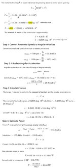
But my numbers seem pretty high. My calculation
Taking a typical Shelby GT500 brake rotor(I know you all have these laying around like me), consider this brake Rotor laying flat on your screen, where z-axis is coming out of the screen, and rotating, with an outer radius is 7.5”, inner radius is 4.5”, thickness is 1.25” and mass of 31.4 lbs, what is the inertia? Then find the torque and horsepower to accelerate the brake rotor to a target rotational speed of 700 rpm to 1500 rpm in 4 seconds about its z-axis. (Basically a tire diameter of 28.5" to get wheel rpm from 60mph to 130mph, gives 700rpm to 1500rpm wheel/rotor speed.

So as the title states I got 175 ft-lb and 36Hp. But torque acting on the hub given a 3.55 rear diff gear ratio, we'll get 49ft-lb and 10.14 Hp is what the engine needs if you go through a 1:1 4th gear ratio. Multiply this by 4 wheels (say rear wheels have 75% smaller brake rotors), you're looking at 172 ft-lb and 35Hp from the engine just to turn the brake rotors. Seems reasonable?
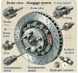
So what kind of system would disengage, Chatgpt solutions:
1. Sprag or Overrunning Clutch
A sprag or overrunning clutch allows torque transmission in only one direction. When braking force is applied, it locks the rotor to the hub, but when no braking force is applied, it allows the rotor to spin freely.
2. Pneumatic or Hydraulic Actuator with a Locking Pin
3. Mechanical Locking Hub (Manually or Automatically Controlled)
4. Electromechanical Braking System (e.g., Electric Park Brake Actuator)
5. Electromagnetic Clutch

Chatgpt creates some strange images but anyway, the system would have to be normally closed for safety. And the added weight is another thing to consider. You need to engage it a split millisecond before the braking event but that should be doable or you can gradually bring the freewheeling rotor to match the hub speed where it would take a lot less torque over the greater time.
I think a synchro dog teeth transmission style system would also work but may not be normally closed. And spinning it up to speed to match the hub speed would have to start before the braking event but on a straight away this is not an issue due to the extra time, but still creates more load on the vehicle. You want the rotor freewheeling when accelerating to save that horsepower and enough to take over another vehicle, once at cruising speed, the system would start to match the rotor and wheel/hub speed.
Kindly discuss.
Edit to add cleaner calculations.
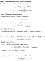
But my numbers seem pretty high. My calculation
Taking a typical Shelby GT500 brake rotor(I know you all have these laying around like me), consider this brake Rotor laying flat on your screen, where z-axis is coming out of the screen, and rotating, with an outer radius is 7.5”, inner radius is 4.5”, thickness is 1.25” and mass of 31.4 lbs, what is the inertia? Then find the torque and horsepower to accelerate the brake rotor to a target rotational speed of 700 rpm to 1500 rpm in 4 seconds about its z-axis. (Basically a tire diameter of 28.5" to get wheel rpm from 60mph to 130mph, gives 700rpm to 1500rpm wheel/rotor speed.

So as the title states I got 175 ft-lb and 36Hp. But torque acting on the hub given a 3.55 rear diff gear ratio, we'll get 49ft-lb and 10.14 Hp is what the engine needs if you go through a 1:1 4th gear ratio. Multiply this by 4 wheels (say rear wheels have 75% smaller brake rotors), you're looking at 172 ft-lb and 35Hp from the engine just to turn the brake rotors. Seems reasonable?
So what kind of system would disengage, Chatgpt solutions:
1. Sprag or Overrunning Clutch
A sprag or overrunning clutch allows torque transmission in only one direction. When braking force is applied, it locks the rotor to the hub, but when no braking force is applied, it allows the rotor to spin freely.
2. Pneumatic or Hydraulic Actuator with a Locking Pin
3. Mechanical Locking Hub (Manually or Automatically Controlled)
4. Electromechanical Braking System (e.g., Electric Park Brake Actuator)
5. Electromagnetic Clutch

Chatgpt creates some strange images but anyway, the system would have to be normally closed for safety. And the added weight is another thing to consider. You need to engage it a split millisecond before the braking event but that should be doable or you can gradually bring the freewheeling rotor to match the hub speed where it would take a lot less torque over the greater time.
I think a synchro dog teeth transmission style system would also work but may not be normally closed. And spinning it up to speed to match the hub speed would have to start before the braking event but on a straight away this is not an issue due to the extra time, but still creates more load on the vehicle. You want the rotor freewheeling when accelerating to save that horsepower and enough to take over another vehicle, once at cruising speed, the system would start to match the rotor and wheel/hub speed.
Kindly discuss.
Edit to add cleaner calculations.
Last edited:


