Continue to Site

Eng-Tips is the largest engineering community on the Internet

Intelligent Work Forums for Engineering Professionals

  • Congratulations KootK on being selected by the Eng-Tips community for having the most helpful posts in the forums last week. Way to Go!

Vehicle Anti-lock brake rotor system, increase horsepower, Brake Rotor takes 175 ft-lbs, 36 Hp to spin up, really? free wheeling the brake rotor

kaazx9r

Mechanical
Jul 27, 2022
34
Hello, I wanted to see if it would be possible to create an anti-lock brake rotor that would unlock on non-braking events to free up the power it takes to spin them to speed.

But my numbers seem pretty high. My calculation

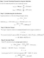
Taking a typical Shelby GT500 brake rotor(I know you all have these laying around like me), consider this brake Rotor laying flat on your screen, where z-axis is coming out of the screen, and rotating, with an outer radius is 7.5”, inner radius is 4.5”, thickness is 1.25” and mass of 31.4 lbs, what is the inertia? Then find the torque and horsepower to accelerate the brake rotor to a target rotational speed of 700 rpm to 1500 rpm in 4 seconds about its z-axis. (Basically a tire diameter of 28.5" to get wheel rpm from 60mph to 130mph, gives 700rpm to 1500rpm wheel/rotor speed.
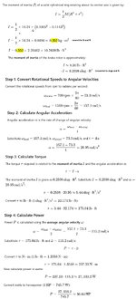
initial_calculations.jpg

So as the title states I got 175 ft-lb and 36Hp. But torque acting on the hub given a 3.55 rear diff gear ratio, we'll get 49ft-lb and 10.14 Hp is what the engine needs if you go through a 1:1 4th gear ratio. Multiply this by 4 wheels (say rear wheels have 75% smaller brake rotors), you're looking at 172 ft-lb and 35Hp from the engine just to turn the brake rotors. Seems reasonable?

So what kind of system would disengage, Chatgpt solutions:
1. Sprag or Overrunning Clutch
A sprag or overrunning clutch allows torque transmission in only one direction. When braking force is applied, it locks the rotor to the hub, but when no braking force is applied, it allows the rotor to spin freely.

2. Pneumatic or Hydraulic Actuator with a Locking Pin
3. Mechanical Locking Hub (Manually or Automatically Controlled)
4. Electromechanical Braking System (e.g., Electric Park Brake Actuator)
5. Electromagnetic Clutch
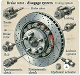
anti_lock_brake_rotor.jpg

Chatgpt creates some strange images but anyway, the system would have to be normally closed for safety. And the added weight is another thing to consider. You need to engage it a split millisecond before the braking event but that should be doable or you can gradually bring the freewheeling rotor to match the hub speed where it would take a lot less torque over the greater time.

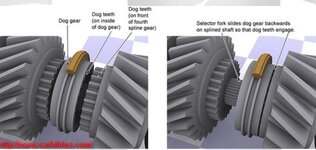
I think a synchro dog teeth transmission style system would also work but may not be normally closed. And spinning it up to speed to match the hub speed would have to start before the braking event but on a straight away this is not an issue due to the extra time, but still creates more load on the vehicle. You want the rotor freewheeling when accelerating to save that horsepower and enough to take over another vehicle, once at cruising speed, the system would start to match the rotor and wheel/hub speed.

Kindly discuss.

Edit to add cleaner calculations.
 
Last edited:
Replies continue below

Recommended for you

You're accelerating from 60 to 130 mph in 4 seconds! No wonder the power seems high.

But all that extra weight will slow you down as well.

Then when you get there the power drops off.

You're mixing all sorts of sets of units as well which makes it harder to follow and I gave up tbh.
 
sorry some just online calculators
Moment of inertia of a hollow cylinder.
answer 8.36ft-lbs^2

The rest are pretty straight forward. Chatgpt gave the same answers as the calculators. Site needs an equation editor to make it easier to follow, i haven't utilized it yet.

Back to the system, you can also use it has a anti-lock braking, when the wheel locks, the system would pulse the brake rotor on and off. It would be better if the system is on the end of the differential like the old jaguars because all that unsprung weight is not good, it is heavy but those itself have their own heat issues.

The system could also help turn in, during understeer, the inner wheel can engage the no-spinning brake rotor, basically having a brake pedal at each wheel.

The system will create some amount of heat as well.
 
My rotor is attached to my wheel, so any inertia calculations should include both. Additionally, braking isn't about stopping the spinning of the rotors or the wheels, it's about stopping the car itself; any calculation related to acceleration is about accelerating or decelerating the car, not the wheels.
 
Thank you, no one said anything about the wheel or braking or slowing the entire car. asking about the rotor.

I’m asking about the turning the brake rotor and what it takes to get it turning. Obviously the rotor accelerates with the car, but that’s a linear motion and will be there no matter what the car is doing. Obviously the wheel has a large amount of inertia to get it turning. But unfortunately I can’t free wheel the tire or wheel of a driven wheel. Would be nice though.

I’m asking about what people think about the values I’m getting the the brake rotor itself. Which to me is pretty heavy.
 
Very interesting idea but since braking is such a critical system, I think the risk/benefit analysis would indicate it is safer to always have the rotors fully engaged. The rotor clutching system would need extremely fast reaction speed and tolerance to shock loading.

Nice diagram.
 
The inertia of the brake rotor is small compared to the inertia of the wheel and tire assembly. Reason: the tread of the tire has the full radius of the assembly contributing to the moment of inertia, and the sidewalls of the tire have most of it contributing. And at least on any of my vehicles, the tire weighs way more than the brake rotor(s).

Probably also going to find that the inertia is small compared to the flywheel and clutch (manual) or torque converter (automatic) or motor rotor (EV) due to those rotating at much higher revs due to the gear reduction between those and the drive wheel(s).

I hate to be a naysayer BUT ... Won't pass FMEA (adds too many failure modes), adds unsprung weight, adds delay time before the brake can be applied, sudden impact inside the engagement mechanism between a fast-spinning wheel and a stopped brake rotor is begging for a piece of the engagement mechanism to break (see: FMEA). And all in an attempt to reduce an inertial load that is a pretty small part of the total and that represents a near-zero load when just cruising down the road at constant speed.

Better to just apply weight-reduction to the vehicle itself, and reduce weight, instead of adding more weight and more complexity.
 
The wheel tire combo is 49.3lbs, versus 31.4 lbs brake rotor, that has a good amount of inertia, 45.64ft-lbs^2 versus 8.36ft-lbs^2(brake rotor), but are my numbers correct?. Which then equates to the tire/wheel (49lbs, outer radius 14" and inner 8.5"), taking 942.75lb⋅ft and 197hp, so i feel the numbers are way high. Back to my initial question, the numbers seem pretty high.calculations.jpg
 
Last edited:
If a brake disk is arranged so that it can apply braking (negative) torque when the vehicle is moving forward and freewheels in response to positive torque, then it will freewheel when trying to brake the vehicle when it is moving backwards.

Your concept is fundamentally flawed.

This should be the end of the discussion.
 
The freewheel lock would have to work for brakes in reverse, too. Neat idea but I think you have popped the giddy balloon . . .
 
I'm not sure if you're getting what I wrote, the system disengages and engages, so there is no moving backwards because rotor is fully locked with the wheel hub when the system engages. I'm talking about non braking events. It better be locked when you brake(reason you want it normally closed), otherwise it would act as you have stated.
 
And as your previous post points out: brakes must work in reverse, too. Neat idea but I think you have popped the giddy balloon . . .
As I stated, the rotor is fully locked with the wheel when the system is engaged. Doesn't matter if you're going in reverse or not. Think of a dog gear teeth on a gear, (one set on the rotor and other set on the wheel hub) ignore the synchros for now:
 

Attachments

  • dogteeth.jpg
    dogteeth.jpg
    87.4 KB · Views: 3
An automotive brake rotor doesn't weigh 32 lb.
15” rotors are pretty heavy. I think it’s not uncommon these days. Camaro’s have 390mm discs. But back to the calculations, anything look off to you all? ( the rotor is weight is exact, unless my digital scale is wrong)
 
Engaging what is effectively a dog clutch when there is a large difference in rotational speed between them, breaks stuff.

You're doing your calculations in imperial units, which are gibberish to me. I have no feel for whether that old-English imperial number is rational.
 
Then i should complain to this calculator


What unit would you prefer the calculator has most of them?
 
OK, I'm gobsmacked by the weight. Meanwhile the rest of the world is fitting carbon fibre wheels to save 10 kg?

Yeah sorry the agony of working in imperial means I have no feel for the right answer.

Wagging it In metric I is about .6 kg m^-2,

T=21*.6=12 Nm
Hence power is 115*12 W, about 1.5 kW, or 2 hp

Well that's different.
 
You are though taking very conservative data.

The brake disc at 32 lbs seems right for this monster of a car, but that is total weight of the disc including the hub. The inner hub hole is 70mm diam or 1.4" radius.

I looked up the acceleration times and from 60 to 130 it takes 8 seconds. So pretty startling alright, but not 4 seconds.

Try plugging those numbers in and see what happens?
 
OK, I'm gobsmacked by the weight. Meanwhile the rest of the world is fitting carbon fibre wheels to save 10 kg?

Yeah sorry the agony of working in imperial means I have no feel for the right answer.

Wagging it In metric I is about .6 kg m^-2,

T=21*.6=12 Nm
Hence power is 115*12 W, about 1.5 kW, or 2 hp

Well that's different.
This seems more reasonable, thank you. Should you use gravity acceleration when doing metric? which would be .6 kg/m^2 x 9.81 m/s^2, which gets you to 5.8 N/m^2 multiply this by acceleration 21 rad/sec gets you 123.6 Nm or 90 ft-lb.
 

Part and Inventory Search

Sponsor