Continue to Site

Eng-Tips is the largest engineering community on the Internet

Intelligent Work Forums for Engineering Professionals

  • Congratulations pierreick on being selected by the Eng-Tips community for having the most helpful posts in the forums last week. Way to Go!

Wall Designed As Strut & Tie 1

Status
Not open for further replies.

MDILY

Structural
Sep 18, 2020
5
AS3600-2018 states that walls to be designed as strut and tie when H/L > 2. Can anyone walk me through how to design shear walls as strut & tie? Some examples will be great.
I understand how to design pile cap or deep wall (or beam) as strut and tie under gravity. But how do I design walls as strut & tie for lateral?
 
Replies continue below

Recommended for you

I understand how to design pile cap or deep wall (or beam) as strut and tie under gravity. But how do I design walls as strut & tie for lateral?

Maybe I am missing something. But if you know how to construct a strut-tie model, what is the difference for which type of load (gravity & lateral) it is subjected to?
 
Haven't done it myself, but I'll through my first thought into the ring. Worst case I'll be corrected and learn something.

As retired suggests, I think the principle will be the same. You'll have a compression strut and a tension tie with node zones at the intersections.

You'll end up with a two member truss in the wall. Apply the lateral load at the top corner, and draw a line down to the opposite bottom corner. There's your compression strut. Your tension tie will be vertical from your applied load down to the foundation.
 
@MDILY

I understand your confusion - not long ago I was the one walking around the office annoying people with this very same question (as I was the only 'un'fortunate person with a mid-rise NCC 2019 project).

Phrases such as "just design it as a strut-tie" or "it makes no difference whether it's a vertical or lateral load" are commonplace responses and they don't really help much as the devil hides in the detail of it. Most/all STM models assume point loads and point supports, which works well for spanning panels and pile caps but then how do you apply it to design of a continuously supported wall panel that experiences a set of UDL loads? The STM-truss approach, whilst useful in dealing with chunky non-flexural regions is really not very appropriate for slender elements. A wall with H/L<2 can still buckle out-of-plane...

Furthermore STM models are typically developed for one particular load combination as geometry of nodes/struts/ties depends on magnitude of loads and thus if you are designing a shear wall for 20...30...40 odd lateral combinations then is the expectation to have as many subtly different STM models for just one shear wall? I find it very difficult to visualise a robust STM framework that can be applied to any building of a large size.

The answer is that nobody really knows. NCC 2019 has been in force for just over a year now and I am yet to certify/review a set of calculations where AS3600-2018 is adequately applied to design of shear walls and words cannot express how keen I am to see a set of such calculations. For the time being I can tell you that people are going along with a push-pull type of approach where you do the following:

0. Do a P/A +- M/Z type of calculation to determine the elastic distribution of stresses in your wall.

1. Do a ULS design check for the axial actions within the outermost 1m strips of the wall using provisions of Section 10 to check for out-of-plane buckling and making sure that the wall has enough reinforcement to transmit the critical tensile action (don't forget that Section 14 now forbids use of low-ductility reinforcement). There are some differences of opinion here sometimes as to whether one should use the critical actions at the very edge of the wall or whether it is appropriate to average across the outermost 1m strip.

2. Do a ULS design check for shear action across the entire wall using provisions of Section 11.

3. Make sure to comply with detailing requirements of Section 14 and try to avoid 50 MPa concrete at all costs. It's difficult to explain to site personnel why they now have to put ligatures into walls.

I personally think that precast core construction will be very difficult to justify design-wise for any mid-rise project designed to NCC 2019. There are a couple more clauses in AS3600-2018 that make it very difficult to design a precast core the way people are generally used to doing it. There are some provisions elsewhere that also come into play that potentially reduce peak tension demand but that's a separate topic. I hope that the above 4 points help - that's my 2 cents and you should absolutely make sure that you and your supervising engineer are both 100% on board with this sort of reading of Section 11.

If I come off sounding critical of the new code I just want to make it clear that I am on board with all of this new stuff. I think that a lot of it will put an end to some of the more 'interesting' design practices that we have going on around here, however that is not to say that the transition is going to be easy for any of the design/construction staff involved. If there are publicly trading companies out there that supply rebar in AUS then I would seriously be interested in investing; steel consumption on site will certainly be impacted when designers start specifying the minimum rebar mandated in Section 14.


For a strut and tie design example for a wall with openings have a look at the example here in section 3.8. Same concept can be followed for walls without openings.

Its related to masonry, and NZ standard. But should give you some guidance.

I think part of the point with the "new" changes in Australia is that they are trying to fundamentally change the way you have previously been detailing and designing concrete structures.

Basically changing things people have been doing wrong for years, the rest of the worlds doing these things, welcome aboard. Certainly some of the new stuff and concepts involved that people are complaining about for seismic design have fundamentally been in our codes in New Zealand for nearly 50 years in one form or another (and obviously have been improved upon continually based on our experiences regarding recent events here).

Unfortunately it might take people dying like it did here to reinforce the importance of understanding and following "the rules" regarding good detailing and design.

I'm the first to agree some of the Australian provisions to a seasoned designer educated and practising in New Zealand are a bit hard to follow. But the concepts and why you are doing things is the same. With no commentary it makes it all much harder to understand though.
 
Thanks for your inputs.

@retired13 & phamENG
The reason why I am not familiar with lateral ones is I haven't seen strut & tie model used for shear walls either on textbooks or real world examples and that's why I am asking for one. One difference between the gravity and lateral one is that with gravity model say pile cap, the support width is known while for say rectangular lateral wall how do you determine the support width? I cannot find anything in regard to this in the section 12.

@BAretired
Thanks for the link, I will have a look.

@captain_slow
Thanks for the suggestion. That's how I designed shear wall. I do understand the logic behind this - because the pull-push N-M iteration method is for flexural member based on plane section assumption, which s not applicable for 'deep' walls but at the same time I fail to see STM computations for shear walls as well.

@Agent666
Thanks for the link.
I agree that the previous standards was poorly written especially when it comes to earthquake but I doubt that strut & tie model are widely used for shear walls outside of Australia but I might be wrong. Do you design shear wall as strut & tie in your projects and what's the workflow is like? I would say it will be onerous for me to be honest.
 
I understand that for this situation you take H as the total height of the wall, not the floor to floor height.
 
It definitely has its place with regard to demonstrating local loadpaths around discontinuities, openings and so forth where normal code equations cannot be applied verbatim. Basically where ever you need to think what is the Loadpath here, you should be considering strut and tie, even if it's just to gain a feel of where the load is going.

Corbels, beam column joints and more importantly diaphragms all make use of strut and tie round these parts on a regular basis.
 
The section basically says

1 - 11.2.1(a) (i) and (ii) if the wall is fully in compression design it as a wall or as a column depending on simplified method versus rigorous.

2 - 11.2.1(b) (i) if the wall goes into tension on one face and is acting as a flexural member, design is as a column in combined axial force and moment

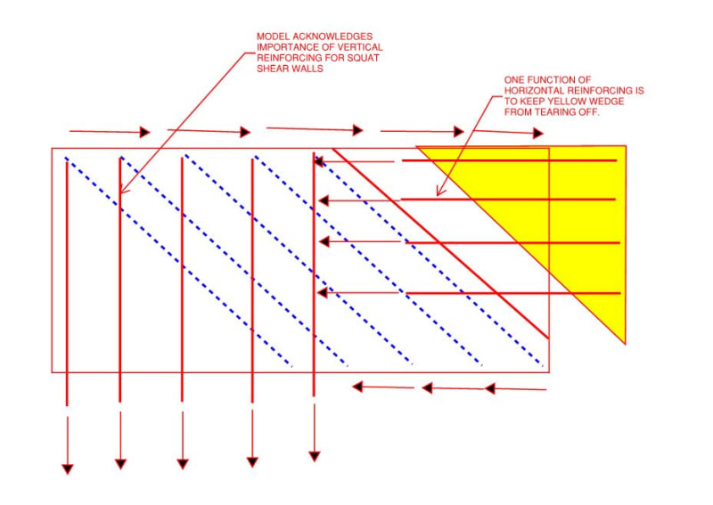
3 - 11.2.1(b) (ii) if the wall goes into tension on one face and it is non-flexural, design it as a deep beam i.e. strut tie.

The old code said the same things, but was more convoluted and harder to understand, eg it suggested for 2 above designing as a beam in accordance with section 8, which does not account for axial compression, so how could you do it, other than to then go to section 10 that accounted for combined axial and compression. The old rule did not make sense. The new one says to go to section 10.

And for 2 and 3 above which was a combined sentence in the old code, it left it to the designer to decide between the 2 options "as appropriate". Maybe people who now do not understand the new code did not understand what was appropriate in the old code and always designed them as columns, incorrectly.

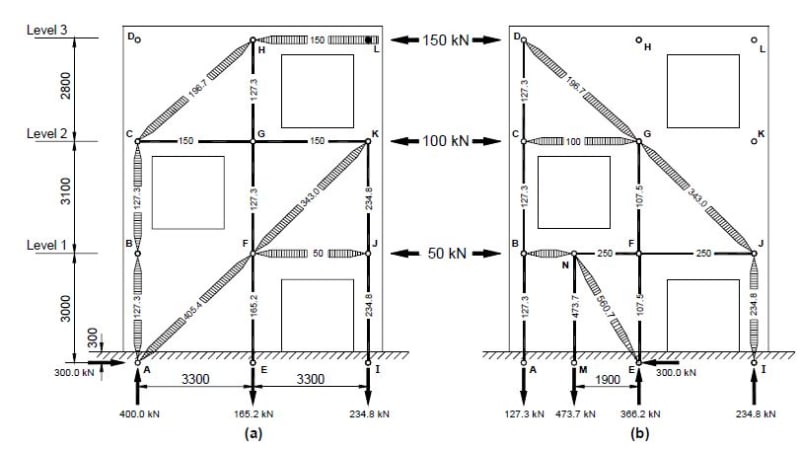
If a wall is 3m tall and 3m long, you cannot design it as a column. It is a deep beam. It has to be designed in accordance with section 12.

That is what "as appropriate" was telling you to do previously, design it in accordance with section 12 in AS3600-2009 clause 11.2.1(b) last sentence!

Nothing has changed in this except the code now defines when section 12 should be used instead of allowing the designer to decide "as appropriate" when they did not understand what was appropriate!
 
Agree and understand that flexural member is not applicable here but at the same, I haven't seen any shear wall computations is done this way for any project although they are 'deep', why is that?
Also, when we work out the lateral loads applied to the shear wall we use 'relative stiffness method' (for rigid diaphragm) which means 'flexural' stiffness will be involved. In another word, we don't model the deep shear wall as trusses to get the distributed lateral loads in the first place.
 
Maybe no-one you know or whose work you have seen understood the meaning of "as appropriate"!

The wording in the code was changed for a good reason in that case!
 
@rapt

Looks like OP has a genuine question that is yet to be answered meaningfully by this forum; plenty of links have been thrown out and a lot of words have been said, however I am yet to see a strut-tie model (or even suggestion of one) that would thoroughly answer the question. How does one really design a wall this way?

@MDILY

Do you have access to an FEA solver that can deal with plates? It can sometimes (not always) be useful to build up a representative plate model and look at principal stresses - direction and magnitude of stresses can imply a suitable strut-tie model. This type of modelling can be tricky as you have to be careful with boundary conditions and application of loads can take non-trivial amount of time.

Beyond this and my original comment I am afraid I don't have anything decisive to offer. Have a look at strut-tie models for beam shear - whatever your model ends up looking like I bet it will have a heap of inclined struts; having said that don't forget that you still have flexural action across the wall that needs to be taken care of (which is not accounted for in beam shear STMs).

I have a good paper on STMs somewhere, I will look for it and will post it here over the weekend. It doesn't answer your questions, but it is a good read with a decent number of examples.

 
captain_slow said:
Most/all STM models assume point loads and point supports, which works well for spanning panels and pile caps but then how do you apply it to design of a continuously supported wall panel that experiences a set of UDL loads?

In the example that Agent666 linked to they just apply the distributed horizontal loads as a point load at the edge of the wall and develop the STM from there.

Capture_mtespi.jpg
 
Just distribute the load between the nodes in some logical manner (usually tributary length between nodes at floor level. Ensure the connected floor can deliver the load in this manner.
 
Noticed that MDILY referred to H/L > 2 in the first post.

He meant H/L <= 2 for strut tie. H/L > 2 is considered flexural.
 
Interesting discussion...

Flipping things into the horizontal realm, what's everyone's opinion on designing slab diaphragms using similar techniques to designing shear walls from FEA output? With many different load combinations, wind/EQ directions and diaphragm eccentricities it would make sense that a "design strip" approach would be more convenient that setting up hundreds of possible STM models.

I contacted CSI recently to ask why they don't report in-plane shear/bending for slab design strips but do report all six design actions (P,T,V2,V3,M2,M3) for wall piers/spandrels. They replied it a feature seldom required and the it's the first time somebody has requested it. Perhaps it's because diaphragm design is seldom considered in any great detail? Setting up 'section cuts' within CSI software can be a real pain...

 
op said:
...what's the workflow is like? I would say it will be onerous for me to be honest.

1) I appreciate your honesty and suspect that is most people's truth on this. A true, formal STM design exercise is often very onerous given current technology. There are times when it's appropriate but, as you probably know, production engineering has to move quickly. Most things need to be ETABS / Excel in order for anybody to make any money.

2) In some jurisdictions, such as my own, there are provisions for Squat Shear Wall Design. This follows a model similar to that shown below wherein:

a) It is acknowledged that a squat shear wall behaves differently from a slender shear wall where conventional, flexural design treatment is appropriate.

b) It provides designers with an appropriately expeditious tool for the design of squat shear walls that is amenable to spreadsheet / software solution.

I've been referring to solutions like this as "Strut and Tie Informed" and a lot of practical design techniques go this way in my experience. You're basically acknowledging the salient features of a strut and tie model without getting waste deep into the weeds of it.

C01_tixm0d.jpg
 
Trenno said:
...what's everyone's opinion on designing slab diaphragms using similar techniques to designing shear walls from FEA output?

I don't recall whether I saw it in ACI or AISC but, someplace, I've seen this codified where they gave the choice of:

1) STM. Painful but it's validity is indisputable.

2) Sectional. Questionable validity given deep beam stuff.

3) Shear Panel. This one surprises me as it's to treat concrete diaphragms much as we do wood and untopped steel deck diaphragms. Slab panels between boundary elements are basically assumed to do nothing other that transfer shear (no axial / no flexural).

My personal view on it:

4) Most diaphragms are stocky enough that I don't feel it necessary to get overly fancy with the shear design. Having a robust load path and capacity for your boundary elements is where extra attention is most warranted. I'm sure that this informed the options above.

5) This is an instance where I'm happy to let designers autonomously decide the limits of applicability for various methods. Obviously, for things like high aspect diaphragms, transfer diaphragms, and swiss cheese diaphragms, STM is surely the way to go and sectional is inappropriate.

6) When I do sectional, I use the reduced lever arm method of old to give some account to deep beam action. It's easy and helps to gentrify the sectional method a bit.
 
Our code in NZ requires us to use strut and tie for diaphragm design, using an approach called pseudo equivalent static analysis (pESA).

Some guidance around how we go about the analysis side of the design is in appendix C5D in this document.
 
Status
Not open for further replies.

Part and Inventory Search

Sponsor