Continue to Site

Eng-Tips is the largest engineering community on the Internet

Intelligent Work Forums for Engineering Professionals

  • Congratulations KootK on being selected by the Eng-Tips community for having the most helpful posts in the forums last week. Way to Go!

Wall Mounted Jib Crane Compression Member Effective Length Factor k should it be 1 or 2

Status
Not open for further replies.

Deension

Structural
Oct 30, 2012
8
Hello Guys,

I am design a wall mounted jib crane (attached) that is in a triangular configuration. The Jib Arm is cantilevering about 17ft give or take; it is tied at about 13' with a tie 1" tie rod that is pin connected to the wall. The Jib is also pin connected to the wall. The angle between the jib and tie rod is about 10 degrees. My question is what k value (effective length factor) to us for design of the jib which is in signaficant compression and some moment.

I am teared between a k=1 for pin - pin condition and k = 2 for pin - free condition. I did come across a paper that uses k = 1 but I am not sure if I should use k = 1 or k = 2 for the designing the jib that is in compression. Any help from you guys would be greatly appreciated.

Best Regards

 
 http://files.engineering.com/getfile.aspx?folder=5326a1f5-dfcc-4dda-84a0-9b890276ca52&file=Jib_Crane.jpg
Replies continue below

Recommended for you

I vote for K=1.

I like to debate structural engineering theory -- a lot. If I challenge you on something, know that I'm doing so because I respect your opinion enough to either change it or adopt it.
 
Thanks Kootk for the reply but is there any justification for your choice of k=1?
 
When you have compression in the strut, the end of the strut will be braced against strong axis tip displacement by a) the load pulling down and b) the tie pulling up. So K=1 for strong axis buckling. I wouldn't do it personally but one could even argue for some fixity at the wall. Often the hinge apparatus there will create considerable fixity.

Weak axis buckling is probably what's making your head hurt. There's really no possibility of K=2 cantilever buckling because the strut is capable of free, rigid body rotation in the weak axis direction. The only possibility is buckling between the ends of the member as represented by the K= 1 case.

If that doesn't answer your question, perhaps elaborate why you think that K=2 might be appropriate and I'll do my best to respond to that directly.

I like to debate structural engineering theory -- a lot. If I challenge you on something, know that I'm doing so because I respect your opinion enough to either change it or adopt it.
 
Thanks Kootk!

You are right I am concerned with weak axis bending. Attached is what I was thinking of when I came up with k = 2. Would the shaft provide a reaction opposite to the thrust (compression)and since one end of the beam is pinned the other end is free to move and rotate would that cause it to have a k = 2. Although your explanation make since but wouldn't the beam bend in the weak axis as drawn (attached).

Once again thank you very much for all your help on this simple yet confusing problem.

Best Regards
 
 http://files.engineering.com/getfile.aspx?folder=b8cf863a-e3c6-4fbd-9cc3-6fcf92458fba&file=jib-effective_length.jpg
Thanks Brad805!

They don't provide the size of the beam to confirm my calculation.

Best Regards
 
You're very welcome Deension. I do see where you are coming from.

Think of it this way. In your sketch, the two forces at the end of the strut are not colinear and therefore not in equilibrium. They would generate a moment about the support hinge that would initiate a clockwise rigid body rotation of the strut instead of internal buckling.

If you rotated both of the forces in your sketch slightly clockwise such that they were colinear, the strut would be in equilibrium. You would also have yourself a sketch of a textbook K=1 internal buckling mode.

You buyin' that?

I like to debate structural engineering theory -- a lot. If I challenge you on something, know that I'm doing so because I respect your opinion enough to either change it or adopt it.
 
@Deension: I was working on my phone when I posted my last response. Somehow, I was only able to see the plan view of your sketch (weak axis). I think that my last comment covers that. As for the elevation sketch, and the strong axis case:

1) Remember that the portion of the strut to the right of the tie rod connection carries no axial load. As such, pure compression column buckling has no meaning there. K=0.

2) About the strong axis, what you've got is a rather complex, cantilever, lateral torsional buckling situation to the right of the tie rod connection. You'll have a K value greater than one for the effective LTB unbraced length. That, however, is a separate thing from compression/column buckling and the K value that goes along with that.

KL for LTB could be very conservatively taken as 2 x (L1 + L2). A more precise estimation would require knowledge of a) the depth of the strut and b) how far the load will be hung below the strut bottom flange.


I like to debate structural engineering theory -- a lot. If I challenge you on something, know that I'm doing so because I respect your opinion enough to either change it or adopt it.
 
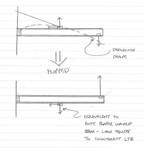
I guess I'm thinking that the Lb for LTB is L1 + L2. If you turn the horizontal beam upside down you essentially have a bottom flange loaed simple span beam.
If the beam tries to laterally buckle (i.e. lay over sideways) the imposed loads on the opposite flanges would resist that rotation.

For the column KL/r I'll have to think about that a bit. If you use 2 x (L2) I think you'd be safe. I'm just not sure if something less than that can be justified.
I'd think there's be some literature out there on jib beam designs.

I also think your vertical plane deflected diagram is wrong. The downward deflection of the beam between column and tie-rod connection should be upward - full negative moment along the full length unless your beam weight is enormous.


Check out Eng-Tips Forum's Policies here:
faq731-376
 
The condition PIN-FREE is fleeting (not completely constrained) so you can't buckle because the structure would have a rigid rotation, as KootK said.

I would go for K=1 (PIN-PIN) and Lb=L2
 
Thank you JAE, BOPECO and Kootk! I really appreciate the discussion that we are involved in.

How can lateral torsional buckling occur when the lateral deflection as you guys say does not occur. As you suggested that the beam will simply rotate and the beam will not bend in weak axis. If that is the case in order the lateral torsional buckling to occur. Three conditions need to occur.

1) beam must deflect or move in the load direction ( happens in this case, and generates moment at tie back rod location)

2) Beam must move laterally or move perpendicular to its cross section ( the beam is connected to pivot shaft, therefore no restraint provided in lateral direction @Kootk what do you think)

3) beam must twist about its longitudinal axis ( the load at the tip of cantilever stabilizes the bottom compression flange and the tie back rod is restrains the tension flange (stabilizing beam)).

@ JAE - if you flip the beam the load would be in opposite direction

I will post a detail sketch lateral so that it could assist you as to what I am thinking.

Best Regards and once again thanks for the discussion!

 
Here's the flipped sketch of the beam.

Flipped_eecqoi.jpg


Check out Eng-Tips Forum's Policies here:
faq731-376
 
Deension said:
2) Beam must move laterally or move perpendicular to its cross section ( the beam is connected to pivot shaft, therefore no restraint provided in lateral direction @Kootk what do you think)

It's best to think of the movement as a rotation about a point in space lying on the same vertical axis as the beam shear centre. Technically, this would be constrained axis buckling (Google that for fun) as the beam would be forced to rotate about the top flange connection to the tie rod.

LTB buckling is definitely a possibility here. It's quite analogous to the argument that I used for the weak axis buckling. An LTB buckling mode involving swing about the hinge is meaningless because it represents rigid body rotation. You will, however, have to contend with an LTB mode where both the hinge and the tie rod connection represent lateral restraints. The hinge will be a lateral torsional restraint. The tie rod connection, while not a lateral restraint in general, would be considered a pseudo lateral restraint for the sake of the LTB mode buckling check. This is just like how, for weak axis compression buckling, the tie rod connection would be considered a pseudo lateral restraint to produce the K=1 buckling mode. Whether or not the tie rod connection represents a torsional beam restraint for LTB is another matter and is the crux of the discrepancy between my and JAE's estimates of effective LTB unbraced length.

Deension said:
3) beam must twist about its longitudinal axis ( the load at the tip of cantilever stabilizes the bottom compression flange and the tie back rod is restrains the tension flange (stabilizing beam)).

As I mentioned above, twist will technically be constrained to occur about the top flange where it meets the tie rod. Minor point. Whether or not the load effectively prevents beam rotation at the tip is a matter of considerable interest and is the source of the discrepancy between my recommendation regarding KL_LTB and JAE's recommendation. If the load can be relied upon to provide rotational restraint, then JAE is correct and the upside down simple span beam analogy would be appropriate. If not, then KL would be something longer than that analogy would indicate. For what it's worth, I suspect that, in most practical applications, the load would provide sufficient restraint. I'm just hesitant to assume that without quantifying it somehow.

I like to debate structural engineering theory -- a lot. If I challenge you on something, know that I'm doing so because I respect your opinion enough to either change it or adopt it.
 
Status
Not open for further replies.

Part and Inventory Search

Sponsor