Continue to Site

Eng-Tips is the largest engineering community on the Internet

Intelligent Work Forums for Engineering Professionals

  • Congratulations KootK on being selected by the Eng-Tips community for having the most helpful posts in the forums last week. Way to Go!

Wastewater Wetwell bellmouth annular velocity

Status
Not open for further replies.

Nutzman

Mechanical
Nov 2, 2020
57
Hi all,

I have a number of sites where the pipework was sized to cater for a flow on the day. Thanks to growing populations, the station needs to be upgraded.
It's easy to increase pump and pipe sizes "in-station" to cater for the increased flows. However what is often ignored is the pipework through the wetwell/drywell wall. and by association the bellmouth in the wetwell.
There are industry standards stating the clearance between the underside of the bell mouth and the wetwell floor. Typically D/2 to D/4.
Invariably what happens is the "100mm" pipe through the wall had a bell mouth with a clearance of (Bellmouth OD - 185mm/2 = 92.5mm underside clearance).
The station is upgraded to a 150mm (pipe through the wall) in station. So the bellmouth should have a clearance of (Bellmouth OD of 245mm/2 = 122.5mm).
But the pipe through the wall and bell mouth were not upgraded, so we have a 100mm pipe/bellmouth with a 150mm velocity.
The question is, does anyone have the formula for the calculate the annular velocity entering the bellmouth.

Thanking you all in anticipation.

Nutzman
 
Replies continue below

Recommended for you

can you sketch this so we can see exactly what you mean and where the velocity is that you're trying to calculate.

"Annular velocity" is what's confusing me as this should be a simple exercise of flow velocity or volume and Id of the pipe equation.

what's the purpose as you can't change pipe size by the look of it in the wet well entrance.

Remember - More details = better answers
Also: If you get a response it's polite to respond to it.
 
Hi LittleInch,

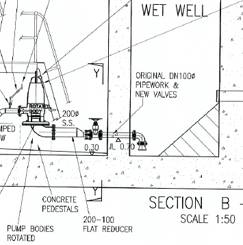
Thanks for coming back to me. Attached is a snapshot of the drywell/wetwell. In this instance the pipe diameter has gone form 100 to 200mm. Essentially what should have been done, was the wall, should have been core drilled to suit the height of the 200mm bellmouth clearance height.
In answer to your question, i am trying to determine the velocity entering the bellmouth (between the floor and the circumference of the bellmouth.
In the above example the initial bellmouth is 92mm above the floor. If a 150mm pipe was fitted the clearance should be 122.5mm thereby maintaining acceptable inlet velocities. But with the clearance still been 92mm and the increased flow to accommodate the "150mm" flow the velocity will increase. Hence looking for a formula to calculate the circumferential velocity (or annular> Perhaps my terminology is not correct)
 
Nothing attached.

If its a jpg file try the Image function so everyone can see it without downloading it.

Remember - More details = better answers
Also: If you get a response it's polite to respond to it.
 
Wondered why I could not see it
Wetwell_htssxr.png
 
The annular area I believe would be equal to:

A = Pi*(D)*(Clearance)

If clearance was equal to D/4 then:

A = P*(D)[sup]2[/sup]/4

or the same flow area of the diameter of the bellmouth. For clearance = D/2 then annual flow area would be equal to twice the flow area of the bellmouth. So it looks like the rule is to maintain 1 to 2 time the crossectional flow area of the bellmouth in the annual inlet area (which gives 0.5 to 1 times the bellmouth crossectional area velocity).

With 4" pipe inlet (including bellmouth, straight pipe, gate valve and increaser equivalent lengths) pressure drop will increase substantially so available NPSH should be checked against pump required NPSH.
 
Hi Snickster,

Many thanks for your thoughts. I had been thinking along similar lines. My thinking was that, if I took a sheet of plastic and wrapped it around the perimeter (circumference) of the bellmouth and cut the sheet off at the height of the bellmouth. Then unwrapped the sheet, I would have an area equal to the flow over a sharp crested suppressed rectangular weir? I know the flow, so could apply the flow to the weir calc and get a velocity.
I ran the numbers. With a 182.5mm Dia bellmouth and a 92.5mm "clearance" I get a velocity of 0.1039 m/s. Sounds awful low, but considering the area and it all collects in the 100mm suction line, the velocity could make sense?

Thanks again for your input.

Regards,

Nutzman.
 
What's the existing flow and the increase in flow?

It is a capital mistake to theorise before one has data. Insensibly one begins to twist facts to suit theories, instead of theories to suit facts. (Sherlock Holmes - A Scandal in Bohemia.)
 
Many thanks for your thoughts. I had been thinking along similar lines. My thinking was that, if I took a sheet of plastic and wrapped it around the perimeter (circumference) of the bellmouth and cut the sheet off at the height of the bellmouth. Then unwrapped the sheet, I would have an area equal to the flow over a sharp crested suppressed rectangular weir? I know the flow, so could apply the flow to the weir calc and get a velocity.

I not sure what you mean by "apply the flow to the weir calc."

The flow area of the space between the diameter of the bellmouth entrance and the bottom of the pit is a sheet wrapped around the bellmouth as you describe. This shape actually forms a small length of a cylinder like the surface of a pipe 92.5mm long.

The surface area of this cylinder is Pi*D*L = Pi*(D)*(D/2) = 3.14*7.18"*(7.18/2) = 81.1 sq. in. = 0.56 sq. ft.

Where Pi*(D) is the length of the circumference and L is the length of the cylinder(clearance).

Velocity through any area is flowrate divided by area in this case it would be Flow/0.56. So say you have 200 gpm flow. To convert to equivalent units of Ft3/Sec:

= 200 gpm (7.48*60) = 0.446 Ft[sup]3[/sup]/sec

Therefore velocity across this area is:

V = 0.446/.56 = 0.796 ft/sec

I used 200 gpm because for the original 4" suction line gives a 5 ft/sec velocity at 200 gpm which is about the maximum velocity used to size a suction line to a pump, so I assume this was the approximate original flowrate in the 4" suction. For a 6" suction line size 5 ft/sec would give a flow of 450 gpm so velocity across bellmouth area is:

(450/200)*(.796) = 1.79 ft/sec

I ran the numbers. With a 182.5mm Dia bellmouth and a 92.5mm "clearance" I get a velocity of 0.1039 m/s. Sounds awful low, but considering the area and it all collects in the 100mm suction line, the velocity could make sense?

What's your new flowrate?
 
Hi Artisi,

Unfortunately this is an old installation. So I've no clue what the original flow should have been.
But taking a guess on a "middle of road" line velocity in the 100mm line ~1.25 m/s. (understanding the self cleansing velocity parameters in the waste water industry are 0.75m/s - 1.8m/s) the flow would be 9.85 l/s.
With the upgrade in the station, the flow is expected to achieve 22 l/s. 22 l/s = 2.8 m/s through the 100mm suction line. Hence me been tasked with investigating the "under performance"?

Hi Snickster,
Many thanks for your detailed explanation. Albeit in Imperial units. But not to worry, I speak Imperial as well.
I think we speak the same language, but with a different accent. You have laid out my thoughts more eloquently. I'll apply my values to your formula and hopefully come up with an answer I can understand?

Thank you all again, for your input on this tricky issue.

Nutzman
 
I don't think the cylinder idea is correct.

If the distance to the floor was say 4D, there's no way you would get an even velocity across that imaginary cylinder.

I think it's more like a cone where the base is the bellmouth and the depth is that D/2. In you case that cone gets flattened a bit. Losses will increase if you double flow. If this is an issue why don't you unbolt that elbow and bellmouth and install something bigger and different? The wall coring is prob too much effort, but you could modify the pipework in the wet well no?

Remember - More details = better answers
Also: If you get a response it's polite to respond to it.
 
Hi Littleinch,

I agree with your thinking. As we all know, the flow velocity in a pipe is highest at the centerline and lowest at the inner pipe surface. So I trust the same principle will apply to the imaginary cylinder scenario.
Essentially what i am trying to determine is the increased velocity coming under the bellmouth, due to the bellmouth/pipe through he wall not been upgraded when the pump and in-station pipework is upgraded.
On the stations I have come across thus far that have not had the bellmouth pipework upgraded they all fail to achieve required/expected flows.
I've checked for minimum submergence to ensure their is no vortex.
But the higher velocities and turbulent flow presented to the pump suction is inhibiting flow.
In terms of wall coring, without increasing that diameter through the wall, the original pipe becomes the pinchpoint. (higher velocities).
If there were enough room within the drywell, the pumps could be moved back and the suction pipe extended, to accommodate the 5 x diameter. But the station was build decades ago, to suit the equipment of the day.

Thank you all for your valued input.
 
Hi Snickster,

I managed to create a dual Imperial/Metric spreadsheet. Once I got it into a digestable format, I note that your calculations (velocity across bellmounth)is based on the the difference of flow? Namely 200 and 450 GPM.
I'm essentially looking for a velocity for the old and new flows? (Separately).

Your thoughts?
 
No the velocity I calculated for both cases is flowrate divided by area not difference in flow. I assume old flow was 200 gpm and new flow is 450 gpm. However 22 l/s is actually about 350 gpm.
 
Suspect you may find guidance on this from the Hydraulic Institute Standards. A great deal of reorganisation appears to have taken place since the 1970s' when everything was in a single voluminous bible. This topic is probably now in a standard all of its own - see HI9.8
 
Hi George,

Many thanks for that guidance. I had a copy of the spec and had perused said document. It's interesting to note that the clearance between the underside of the bellmouth and floor is listed as 0.3D to 0.5D. Whereas other literature (possibly '70-'80's) state 0.2 to 0.4D.
But the Hydraulic institute document recommends the ideal velocity (across the bellmouth) as 1.7 m/s.
However in order to calculate the ~1.7 m/s there is a rather complex formula, that calls for a f = Function, Nt = Circulation number, T = Circulation (2πrVt for concentric flow about a point with a tangential velocity Vt at radius r).
Sounds like you need to add in your IQ and divide by your shoe size?
I'm sufficiently confused for today. I'll try again tomorrow.

Regards,

Nutzman
 
Several types of pump intake basins are briefly described together with advantages and limitations for use. Dimensions are given in terms of D, the outside diameter of the suction bell of the pump. The ANSIHI 9.8 standard should be consulted.

Table 12-1. ANSI/HI 9.8-1998 Recommended Velocities for Pump Intake Bells, Based on Bell OD

Picture22_hjtdjq.png


Pumps are suspended (usually by a platform) in a body of water with no confining walls or other flow guiding structures. Unconfined pump intakes are inexpensive and useful for lagoons, lakes, rivers, and canals. Ice, debris, and fish that must be screened ahead of the pumps are of particular concern and require special consideration.
Design
Details of requirements are given in ANSI/HI 9.8.2.7-1998. Submergence requirements in unconfined (and, indeed, in all types of) pump intakes are given in ANSI/HI 9.8.2.7.4-1998 and by Equation 12-1:

S/D = 1 + 2.3 F

where S is submergence, D is outside diameter of the suction bell, and F is the Froude number (dimensionless) given by:

F = V / sq rt (g * D)

where v is the average velocity at the mouth of the suction bell, g is the acceleration due to gravity, and D is the outside diameter of the suction bell.
 
Hi Bimr,

Thanks for that input.
As per the image posted earlier, the site was a wetwell/drywell installation.
On further investigation it appears that although the line velocity in the pipeline through the wall is within the above limits, the lack of 5 to 10 times pipe diameter straight before the pump suction (in order to allow the liquid flow to become stable), including 2 x 90 degree change of direction (in the same plane), collectively contribute to the pumps poor performance. Along with a borderline size of rising main and possible air release valves not functioning properly. So yes, a whole cocktail of issues to consider.
 
If you have space I would insert a flow conditioning plate in that flange between elbow and pump unless the water has a lot of gunge in it....

Could the pump be horizontal? Would eliminate one elbow at least.

Remember - More details = better answers
Also: If you get a response it's polite to respond to it.
 
Hi Littleinch,

The product is sewage. So any form of flow conditioning is going to block up.
The pump supplier, has a trolley mount horizontal version. But then we got to modify the discharge pipework.
 
Status
Not open for further replies.

Part and Inventory Search

Sponsor