Continue to Site

Eng-Tips is the largest engineering community on the Internet

Intelligent Work Forums for Engineering Professionals

  • Congratulations waross on being selected by the Eng-Tips community for having the most helpful posts in the forums last week. Way to Go!

Web parallel stiffeners

BLUEPUPIL

Structural
Mar 29, 2015
13
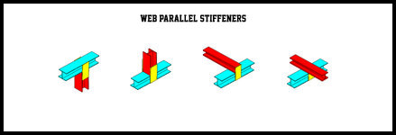
Adding transverse stiffeners perpendicular to a web
(I beams and columns) stiffen the web against out
of plane deformations. What about adding only
transverse stiffeners parallel to the web? It’s a one
storey project involving 6м span, RC columns, simple
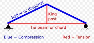
steel king post roof truss (not tied king post) consisting
of HEA profile. Local steel contractor is …. I want to
approach this project differently. Simple, easy to
fabricate and reliable steel connections. What do you
think, is it feasible to satisfy AISC, EC3?

707.jpg
 
Replies continue below

Recommended for you

The yellow plate won't be very efficient because it establishes an alternate load path through the least stiff part of the blue beam, via flexure of the blue beam's flanges. If you consider it like a pair of springs in parallel, where one is much stiffer than the other, the stiffer spring with take proportionally more load.
 
The good doctor has been too congenial here. I'm afraid that this is a terrible idea. The whole point of stiffeners is:

1) To move loads around via in plane stresses in the various plate elements (axial / shear/ maybe in plane bending) and, more importantly;

2) To NOT move loads around using out of plane flexure in the various plate elements as Dr.Z mentioned.

Your details are the reverse of this. Yeah, you can do anything if there's a great reason to do it and you analyze if properly. But, so far, that's not what this situation sounds like to me.

I vote a strong NO on this proposal.
 
I agree with the comments above.

But I would add that sometimes "web stiffeners" are used to stiffen up the opposing flange and prevent rotation of the flange and twist of he section. Normally for LTB reasons. In this case I believe these plates accomplish that. Still I don't see the point of this approach.

As an aside I see web stiffeners used FAR FAR too often in unnecessary circumstances by many engineers and steel detailers. If you are using them commonly for simple connections then you really should be running a few sanity checks on whether they are needed.
You mean to tell me a 3/8" stiffener at every single beam reaction is unnecessary? :ROFLMAO:
 
You mean to tell me a 3/8" stiffener at every single beam reaction is unnecessary? :ROFLMAO:
A "3/8 stiffener"? That is rookie level. ;)

An enthusiastic engineer/detailer can easily fit in four in the examples above!
 
DrZoidberWoop gave brilliant explanation.
KootK (as always) was clear and convincing.
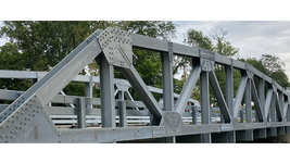
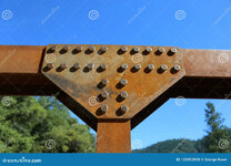
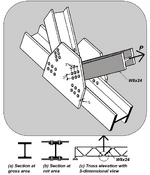
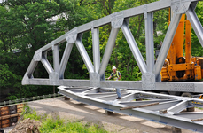
Call my anxiety persistence, but after some
digging, I have came upon some bridge
gusset plates and hot-rolled, open I sections.
To my humble understanding, pictures (to
some degree) represent the idea of "out of
plane flexure". And yes, its not a bridge, but
my intuition is leading me to the question,
why its used in bridges, but its not
appropriate for trusses?


1.png2.png3.jpg4.png5.png
 
Axial loads are mostly assumed to transfer via flanges. The shortest explanation is that you should avoid transferring large axial loads into the flimsiest part of a supporting member because of 1) unacceptable structural performance and 2) reinforcement costs.

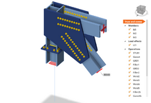
Also, your latest photos all show the bridge's diagonal members in a "rotated" position w/ flange toes oriented vertically.
The column support in your FEA/BIM model does not match the orientation of any of the bridge members shown.
 
To my humble understanding, pictures (to
some degree) represent the idea of "out of
plane flexure".

You are incorrect in that. Because the member forces being transferred are axial and shear in nature, the same is true of the forces moving through the gusset plates. The stresses being transmitted through the gussets, and within the plate elements of the connected parts are all "in plane". So the truss joint condition is very much an exemplar of:

1) To move loads around via in plane stresses in the various plate elements (axial / shear/ maybe in plane bending) and, more importantly;

2) To NOT move loads around using out of plane flexure in the various plate elements as Dr.Z mentioned.

This is absolutely something that you want to have a lock on with respect to the principles involved. Keep asking questions until you've got it sorted to your satisfaction.
 
What about adding only transverse stiffeners parallel to the web?
It’s a one storey project involving 6м span, RC columns, simple
steel king post roof truss (not tied king post) consisting of HEA profile.


1.jpg

..... the member forces being transferred are axial and shear in nature,
the same is true of the forces moving through the gusset plates. The
stresses being transmitted through the gussets, and within the plate
elements of the connected parts are all "in plane".


What about adding only transverse stiffeners parallel to the web?

Yes, you can BLUEPUPIL, but please call them gusset plates and
make clear that it’s a truss (axial tension and compression).


View attachment 2.jpg
 

Part and Inventory Search

Sponsor