Eng-Tips is the largest engineering community on the Internet

Intelligent Work Forums for Engineering Professionals

  • Congratulations waross on being selected by the Tek-Tips community for having the most helpful posts in the forums last week. Way to Go!

Weight Distribution Over Six Points 6

Status
Not open for further replies.

Mernok1

New member
Dec 13, 2021
5
0
0
GB
Hi Everyone,

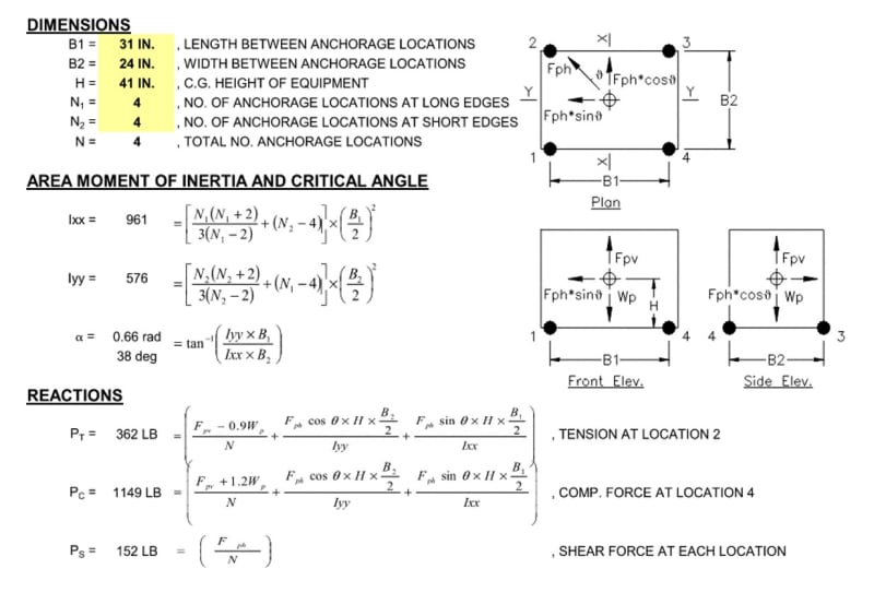
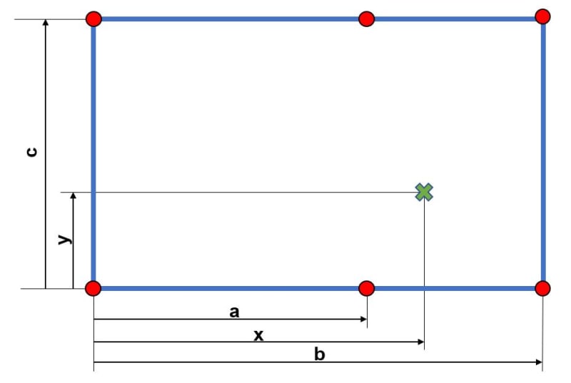
I have a structure supported by six legs that are bolted to the floor. The top view of this setup is shown below. The center of gravity of this structure is marked with a green X, the fixed support legs are shown with red points. I would like to work out the force exerted on the floor by each leg.
x is bigger than a but smaller than b.
What is the best way to approach this problem?
CG_c6mnnu.jpg

I have tried to derive an equation for this but as you can guess, I didn't have any luck.
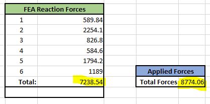
I understand that I could go down on the FEA route but what I would like to get out this is an equation system that I can use in Excel when the numbers change.

Many thanks for your help.
 
Replies continue below

Recommended for you

Are we to assume that the plate on top of the legs is sufficiently rigid to distribute the loading to the legs? Otherwise it would be a true function of actual load distribution and direction of the framing members for the plate.

for example, if there are joists that frame the plate (platform) and they run up-down on the page then you could have the bulk of the load going to the middle two posts. However if they run left-right on the page, then almost 100% of the load would be resisted by outer 4 posts.

Really there's not enough information about the problem at hand to provide good guidance.
 

If the plate may be assumed rigid and the legs are identical, you may find the force exerted on legs with linear distribution.

Locate the neutral axis of six legs X-X and Y-Y , calculate the moment of inertia of six legs Ixx , I yy and shift the force ( W) to the center with moments Mx= W*ey and My = W*ex

Axial load for any leg Pn= W/L +,- Mx*yn/Ixx +,- My*xn/Iyy

Pls look page 18 of the following doc.
 
P1 = P*k/d1

d1 = distance from load to pt1 = sqrt(x^2+y^2)

then sum all 6 reactions P*k*(1/d1+1/d2+...) = P
and k = 1/(1/d1+1/d2+...)

another day in paradise, or is paradise one day closer ?
 
I don't know that considering as a bolt group is right. bolt group loading tends to be load proportional to distance. here I think it's reasonable for the nearer supports to react more load.

another day in paradise, or is paradise one day closer ?
 
the correct way is to write out the equations of equilibrium, only three are effective (FZ, MX, MY)
so the problem is triply redundant.

one way to solve is with matrix math, a least squares approach, see attachment.
another is to assume linear displacements, which I think becomes load inversely proportional to distance.

another day in paradise, or is paradise one day closer ?
 
 https://files.engineering.com/getfile.aspx?folder=e4def362-ba98-4253-abfb-9a7d2a27a066&file=Least_squares_solution_to_over-defined_set_of_linear_equations.mht
I think the stiffness of the blue gray beams/plate/structure is not infinitely stiff.
If it is very stiff That may result in the CG not acting like a point mass where you've indicated.
I think when installing the six red support legs there is a better than middlin' chance that some will not take their fair share, one or two may stand so proud they take nearly all the load, or some may not even touch the floor at all.

Thus one possibility is the load from the CG may be distributed between the four right hand support leg dots. And maybe even on just 3, or even TWO of those 4.
2 or 3 or 4 simple sum-of-the moment / force distribution calcs using differing four support legs will define a few possible loadings for the support legs. then just pick the worst case for each leg.
You did not say what you intend to do with the support loads, but I'd design all the supports and their footings/pads the same, and for the very worst load. I predict Asking the steel fabricator or contractor to keep track of six or even two different supports/footing is asking for trouble.
 
I've designed/analyzed quite a few equipment anchorage/isolation setups and these are the formulae i've used to determine anchor forces (these assume EQUAL spacing between anchorages - sorry, OP). It is as HTURKAK describes. The calculations assume a rigid body attached to rigid supports. The force calculations may or may not be applicable to your problem as they include baked-in ASCE-7 seismic load combinations.

point_inertia_fyctm2.jpg
 
Like the others, is start with an elastic method load analysis (Alex T's bolt group or CRSI's pile group spreadsheets being convenient tools).

From that starting point, I agree that some modification of the results for plate rigidity or leg length are likely appropriate. I'd accomplish that by engineering judgement, relying on some info that has not yet been presented here.

----
just call me Lo.
 
Thank you for response guys. The requirements for this project has changed (as always) since my first message and I ended up generating and FE model in ANSYS.
This model is a bit more representative to the reality. You will find several load cases if you open the file. My reaction forces are short of 1500N roughly unfortunately. I have tried to run the simulation with different load cases but there was always a significant amount of reaction force missing. I am not entirely sure what’s causing this. Would someone be able to take a look at to see find the problem with the simulation?
Capture_y50yzw.jpg


Thank you for your help.
 
"This model is a bit more representative to the reality." ... no it isn't. there is "clearly" a problem with a model where reaction .NE. applied load. Clearly, since the FEA balances (it Has too) there is a seventh support reacting some applied load. You are better off, IMHO, in solving this by hand (since it is QED), and then (if you want the practice) solving with FEA.

another day in paradise, or is paradise one day closer ?
 
Well. I messaged in my previous comment that there is a problem with it as you pointed out. Otherwise, I wouldn't have shared it on this forum.
 
yes, but you start with the quote, which is wrong.

and this is a "bad" way to approach the generalised situation (which is what I thought you were after when you used variables for dimensions).
this is "easy" to put into excel ... define the geometry (positions of the 6 legs, position of the load) and excel can calculate the results.
I would start with a s/sht that had 4 reactions ('cause it's easier to check) then make a 2nd sheet for 6 reactions.

I suspect you have an errant constraint (maybe AUTOSPC ?). Which FEA are you using ? There should be a table that shows the sum of the input loads and the sum of All the reactions and their difference, which Has to be zero (or round-off error).

another day in paradise, or is paradise one day closer ?
 
Hi Mernok1

I have a method in mind using compatibility but I need the dimensions of the structure, centre of gravity and load applied, I will share when I get down to calculating the reactions and making sure that what I am proposing is reasonably correct.

“Do not worry about your problems with mathematics, I assure you mine are far greater.” Albert Einstein
 
Hi Mernok1
I would expect any decent FEM software to solve this with a difference between allied load and sum of reactions < 1%, probably < 0.1 %. If you are using Ansys you are not using it properly. Maybe, as rb1957 suggests, some AUTOSPC is "stealing" the load.

If you neeed a quick result I suggest doing it by hand, as already mentioned. But if you want to use FEA, by all means. The model you have may be more geometrically correct but the results are off. Before you use any reults you need to find the missing load and ensure that the load and boundary conditions are correct. There is no way around that problem.

Good Luck

Thomas
 
well ... anything can be assumed to be anything. you "can" assume the plate is rigid, then check simply by raising one corner and seeing if "plane section remain plane". you can assume rigid then use scales to measure to loads and compare with predictions.

another day in paradise, or is paradise one day closer ?
 
Status
Not open for further replies.
Back
Top