Eng-Tips is the largest engineering community on the Internet

Intelligent Work Forums for Engineering Professionals

  • Congratulations waross on being selected by the Tek-Tips community for having the most helpful posts in the forums last week. Way to Go!

Weight Distribution Over Six Points 6

Status
Not open for further replies.

Mernok1

New member
Dec 13, 2021
5
0
0
GB
Hi Everyone,

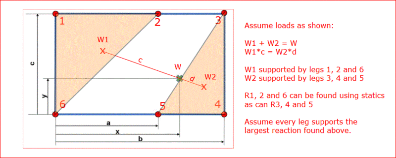
I have a structure supported by six legs that are bolted to the floor. The top view of this setup is shown below. The center of gravity of this structure is marked with a green X, the fixed support legs are shown with red points. I would like to work out the force exerted on the floor by each leg.
x is bigger than a but smaller than b.
What is the best way to approach this problem?
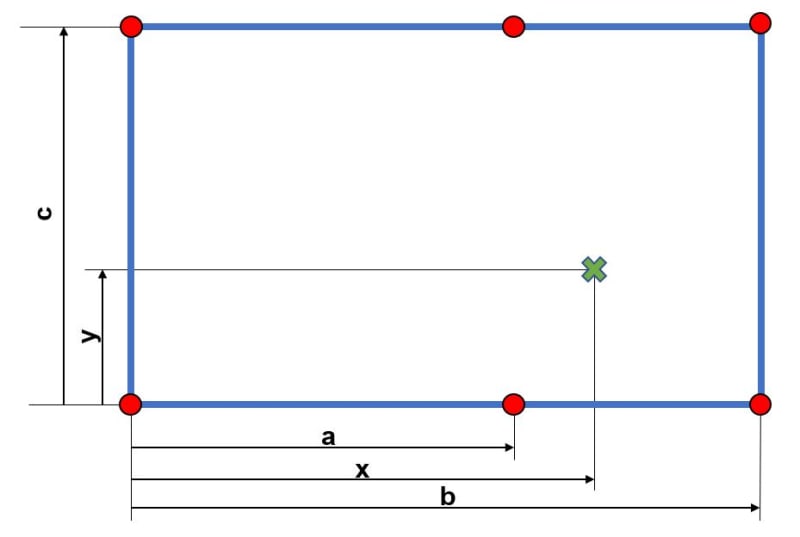
CG_c6mnnu.jpg

I have tried to derive an equation for this but as you can guess, I didn't have any luck.
I understand that I could go down on the FEA route but what I would like to get out this is an equation system that I can use in Excel when the numbers change.

Many thanks for your help.
 
Replies continue below

Recommended for you

If the plate is assumed to be rigid, the assumption is wrong! That is because the plate is not rigid. I'm somewhat surprised that this needs to be said.

BA
 
I do not believe there is any general solution to your problem. The answers will depend on the exact loads applied at exact locations and to the exact stiffness of every part of the structure.

This problem is very similar to how do you calculate the loads in rigging when lifting large heavy objects. Levers and fulcrums are used to remove the unknowns in cable lengths structural stiffness. You cannot do that for your problem. Your answers are only as accurate as your assumptions. In this case your assumptions are not likely to be very accurate.
 
I'd concentrate on coming up with a conservative solution to the problem rather than numerical accuracy.

A black swan to a turkey is a white swan to the butcher ... and to Boeing.
 
Reactions of a three legged table can be determined by statics, whether the plate is rigid or flexible and whether the legs are precisely the same length or not. The same is not true for a four legged table and certainly not for a six legged table.

A four legged table with load W placed dead center might resist W/4 per leg, but if one leg is slightly shorter than the rest, two legs could carry W/2 each while the others carry no load. Any attempt at calculating the actual reactions is futile.

BA
 
I'm alittle surprised by that post.

If the legs are of different lengths then the table will adjust itself until 3 legs are on the ground, and the loads are still statically determinate. I've never seen a table balance itself on two legs (despite what calcs say could happen).

In my experience any reasonably practical table top is near enough "rigid", and would use this assumption ("plane sections remain plane") to determine the loads for the 6 legs and be confident that I'm well within 10%. As said above, a test would confirm the validity of the assumption.

another day in paradise, or is paradise one day closer ?
 
b1957 said:
I'm alittle surprised by that post.

If the legs are of different lengths then the table will adjust itself until 3 legs are on the ground, and the loads are still statically determinate. I've never seen a table balance itself on two legs (despite what calcs say could happen).
We are both a little surprised.

Have you ever sat at a table where one of the legs was short, or the floor was uneven, and the table kept rocking back and forth as people on opposite sides of the table leaned on their side?

You have never seen a table balance itself on two legs because its equilibrium is unstable when the c.g. of load is aligned with two diagonally opposite legs. One leg is off the floor and has zero reaction. One leg may be on the floor but has no reaction. The entire load is carried by only two legs.

If the c.g. of load is eccentric, but within the triangle joining the three loaded legs, the load is supported by three legs, not four. As stated earlier, tripod reactions can be calculated by statics.

For a four legged table, individual reactions can vary between 0 and W, depending on the load location.


BA
 
of course I've sat at a wobbly table. you wrote "two legs could carry W/2 each", which is the correct solution of an ideal situation (akin to spherical chickens in a vacuum).

your characterisation that no table can be rigid is similarly correct in a theoretical sense. In a practical sense, any (well, nearly any) usable table will be stiff enough to be considered rigid. As I said, assuming rigid will IMHO give reactions that are within 10% of the actuals.

Yes, the reactions change as the location (and magnitude) of the load changes ... but nothing that can't be worked out in a s/sht (assuming a rigid table). With more work and problem definition you could work with a flexible table, but then FEA would probably be the better route.

another day in paradise, or is paradise one day closer ?
 
Hi, I thought I’d just contribute to the original request, namely what type of hand calc approach could be applied to the problem. These equations may be of use.
The location of the applied forces are to be given in a global coordinate system, as well as the location of the six supporting legs. The legs can be viewed as a bolt group, placed in the x,y plane. The x,y coordinates of the bolt group centre (BGC) is first found. This is based on bolt x and y distances. In addition, to represent stiffness, a weighting factor can be included (section area or shear / axial stiffness). Knowing the BGC, moments about the x, y and z axis are calculated.
To react out Mz, the assumption that each bolt reaction force is proportional to radial distance from the BGC is made. Based on this, the following is applied.
Pr(i) = Rz.r(i), i for individual bolt number.
If weighted, use Pr(i) = Rz.r(i).A(i), if area. Note that Pr(i) acts at the bolt position and is normal to the radial arm of the individual bolt.
Mz(i) = Pr(i).r(i)=Rz.A(i)r(i)^2
Applied moment Mz = Rz.Sum[A(i).r(i)^2]
Sum[A(i).r(i)^2] = Sum[A(i).[(x(i)-x’)^2+(y(i)-y’)^2]], where x’ and y’ are bolt group centre (BGC) coordinates. Rz can be found and used to find Pr(i). Components in the x and y coordinate system will be needed. The applied forces in the x and y directions are distributed to each bolt, incorporating any weighting.
Forces in the z direction, due to moments about x and y, can be found using the following.
Pz(i) = Rx.(x(i)-x’)-Ry.(y(i)-y’)
Note, Pz(i) can include a weighting factor (area, axial stiffness), and x’,y’ are the BGC coordinates.
Mx(i)=Pz(i).(x(i)-x’) and
Mx(i)=Rx.(x(i)-x’)^2-Ry.(x(i)-x’).(y(i)-y’)
My(i)=Ry.(y(i)-y’)^2-Rx.(x(i)-x’).(y(i)-y’)
You need to sum the individual bolt Mx and My moments, giving Ixx, Iyy and Ixy terms. Rx and Ry can be found by matrix methods. The two equations used are where the total moments are equated. The applied Pz force is distributed to the bolts and the moment / axial components combined.
I hope you find this helpful. Check the calcs to make sure you’re happy with the approach and if it is applicable to your case.
 
Mernok1 said:
I have a structure supported by six legs that are bolted to the floor. The top view of this setup is shown below. The center of gravity of this structure is marked with a green X, the fixed support legs are shown with red points. I would like to work out the force exerted on the floor by each leg.
x is bigger than a but smaller than b.
What is the best way to approach this problem?

There is no unique solution. It depends on the stiffness of the supported structure as well as the distribution of load, not just its center of gravity.

The solution proposed by Stress_Eng is similar to the instantaneous center method for a bolt group. In that case, there is a known moment about the BGC and the plate is properly deemed to be rigid. In the current case, M[sub]x[/sub], M[sub]y[/sub] and M[sub]z[/sub] are all zero; there is no applied moment. The plate is not rigid as it can bend between supports. If it were truly rigid, why use six supports? Three would be enough, but four would make for better symmetry, one at each corner.

With three supports, reactions can be determined by statics alone. With four, assume the load is carried by three supports and make the fourth the same as the worst case (a little conservatism never hurts).

BA
 
Hi, just wanted to give some food for thought, for yet another possible hand calc approach. The plate could be visualised as six springs (joined at cg and individually fixed at legs), each representing load path regions of the plate. Each will have a x and y direction spring stiffness, based on their combined axial and shear deflection capabilities. If needed, a z stiffness could be calculated, based on cantilever bending (fixed at cg) and possibly shear (short beam). A load split can be determined, based on equal x,y,z displacements.
 
If the only forces under consideration are gravitational, z stiffness is the only one relevant. Without some information about the stiffness of the structure being supported and the distribution of load, there can be no unique solution.

BA
 
Hi, just wanted to expand a bit on the moments generated when viewing the plate as a bolt group. If we are only considering a gravity force acting at the cg, the BGC will be offset to the cg (cg location relative to BGC), thus Mx and My moments will be generated about the BGC. If forces were to be applied in the x and y directions, they would produce an Mz moment, and, if placed away from the surface (having a z location) then they would also generate Mx and My moments. Just clarifying what needs to be taken into account when calculating your moments about the BGC.
 
Hi, I have one other possible hand calc approach you may consider. If the structure around the plate profile is considered to give a simply supported condition, then you could consider applying the principles of rectangular plate bending theory. The approach can accommodate numerous types of loading configurations (uniform/ tapered pressure distributions, singular / numerous variably placed point loads). I would suggest referring to references such as Timoshenko. The principle would permit you to determine, under your loading condition, the distributed shear about the profile of the plate, which you could sum up between the legs, find the centroid of the load between the legs and proportion relative to distance.
You could go one step further. Permitting the plate to bend will allow the plate to shorten in length, in both the x and y directions. This change in length can be found, and used in conjunction with the leg displacement stiffnesses to determine leg attachment reaction forces in the x and y directions.
 
Four legs arranged in a square pattern, loaded with gravity force W at the center, i.e. at the intersection of both diagonals, is a perfectly symmetrical structure. You might think that each reaction would be W/4, but that is not necessarily true. If all legs are precisely the same length, it would be true, but if one leg is a micron shorter, no load will be carried by it and no load will be carried by the leg on the other end of the same diagonal until the two legs which carry all of the load shorten by one half micron.

Installers do not work with such extreme precision. One leg might be one or two mm shorter than the rest, in which case, two legs carry W/2 each and two legs carry no load. To be prudent, one should design all four legs for W/2 because the location of the short leg is unknown in advance.

In the case of four legs arranged in a square pattern, loaded at the center, each leg should be capable of supporting W/2. If the load is on a diagonal but not centered, one leg could carry more than W/2. Some conservatism is necessary when calculating reactions.

BA
 
Has Mernok1 got the luxury of being able to alter the structural configuration, and reconfigure the plate structure to make the cg coincide with the BGC? If so, 4 legs would make the situation so much easier!

The original post states 6 legs are all bolted to the ground. This therefore implies that all 6 legs are active in reacting to the applied load. The post also implies that the cg is not in the centre of the plate. If the legs are of different lengths, the act of bolting them to the floor would introduce build stresses into the structure, due to forced displacements. Can shimming be introduced, to reduce any build misalignment? If manufacturing tolerances are to be included in the analysis, the forces required to displace the plate, to allow the legs to close any gaps would need to be determined. Once these forces have been derived, reactions due to applied loading would need to be superimposed.
 
I agree with BARetired. His particular case of a table with 4 legs, for which 1 has a smaller length and 2 carry together all the load, show that the result is very sensitive to the boundary conditions and the theoretical model described above is not precise.


The expression, "As true as a trivet", comes to mind.

Rather than think climate change and the corona virus as science, think of it as the wrath of God. Do you feel any better?

-Dik
 
Stress_Eng said:
Has Mernok1 got the luxury of being able to alter the structural configuration, and reconfigure the plate structure to make the cg coincide with the BGC? If so, 4 legs would make the situation so much easier!

The OP does not mention a plate structure. He says this:

Mernok1 said:
I have a structure supported by six legs that are bolted to the floor.

Could be any kind of structure. Possibly the six points are required to satisfy the attachment points of a mechanical unit, such as a pump.

Four legs does not make it any easier to calculate reactions, as explained in my last post.

Stress_Eng said:
BA in red[/color]]The original post states 6 legs are all bolted to the ground. This therefore implies that all 6 legs are active in reacting to the applied load. The OP may wish that to be the case, but it is unachievable by average workmen.

The post also implies that the cg is not in the centre of the plate. It does not imply that; it states that.

If the legs are of different lengths, (as they are bound to be) the act of bolting them to the floor would introduce build stresses into the structure, due to forced displacements. Displacements are not forced if the structure is rigid.

Can shimming be introduced, to reduce any build misalignment? Certainly it can, but it won't be enough to permit precise calculation of the six reactions.

If manufacturing tolerances are to be included in the analysis, the forces required to displace the plate, to allow the legs to close any gaps would need to be determined. Once these forces have been derived, reactions due to applied loading would need to be superimposed. It's easier to overestimate the reactions and make all legs the same (a little conservative, but sensible).

BA
 
Status
Not open for further replies.
Back
Top