Continue to Site

Eng-Tips is the largest engineering community on the Internet

Intelligent Work Forums for Engineering Professionals

  • Congratulations GregLocock on being selected by the Eng-Tips community for having the most helpful posts in the forums last week. Way to Go!

Weight Distribution Over Six Points 6

Status
Not open for further replies.

Mernok1

New member
Dec 13, 2021
5
Hi Everyone,

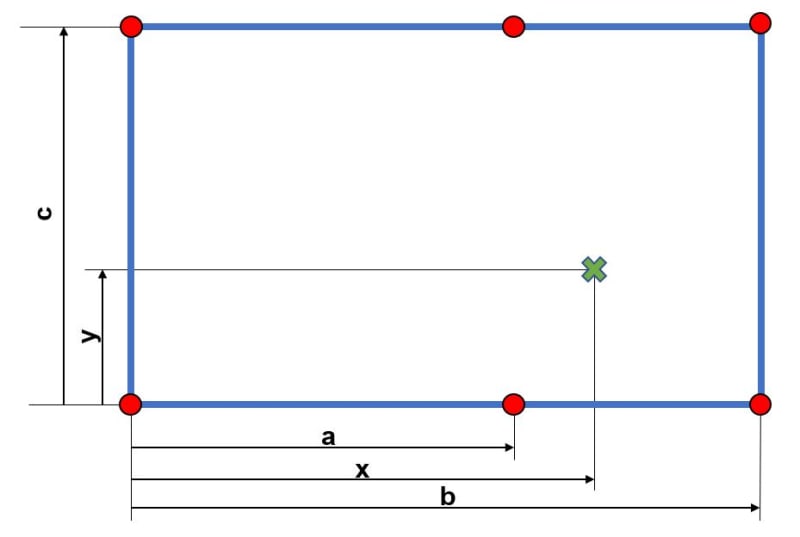
I have a structure supported by six legs that are bolted to the floor. The top view of this setup is shown below. The center of gravity of this structure is marked with a green X, the fixed support legs are shown with red points. I would like to work out the force exerted on the floor by each leg.
x is bigger than a but smaller than b.
What is the best way to approach this problem?
CG_c6mnnu.jpg

I have tried to derive an equation for this but as you can guess, I didn't have any luck.
I understand that I could go down on the FEA route but what I would like to get out this is an equation system that I can use in Excel when the numbers change.

Many thanks for your help.
 
Replies continue below

Recommended for you

that looks elegant (and obtuse) but "c" and "d" are indeterminate.

there are, of course, a multitude of ways to address this indeterminacy. But none are much closer to a solution.

we are, IMHO, making this problem needlessly difficult (when we talk of 1 leg being 1 micron less than the others ... why not then also talk of a surface not being perfectly flat ?). The simplest assumption is to assume the table rigid (and the surfaces of the table and the ground being flat) and solve assuming "plane surfaces remain plane". Yes, we are told nothing about the table (nor the ground), but we can still assume simplifications, and state our assumptions.

another day in paradise, or is paradise one day closer ?
 
rb1957 said:
that looks elegant (and obtuse) but "c" and "d" are indeterminate. I am assuming that the load "W" is the sum of two separate units, one each side of the central legs. That being the case, "c" and "d" would be known. If that is not the case, why use six legs? Four would make more sense.

there are, of course, a multitude of ways to address this indeterminacy. But none are much closer to a solution. If you are expecting an exact solution to the magnitude of each reaction, you will be disappointed. The indeterminacy remains a problem because of the inability of installers to avoid having legs of slightly variable length.

we are, IMHO, making this problem needlessly difficult (when we talk of 1 leg being 1 micron less than the others ... why not then also talk of a surface not being perfectly flat ?). Mechanical units resting on a surface which is not flat would result in precisely the same problem, I agree completely.

The simplest assumption is to assume the table rigid (and the surfaces of the table and the ground being flat) and solve assuming "plane surfaces remain plane". Yes, we are told nothing about the table (nor the ground), but we can still assume simplifications, and state our assumptions. Your assumptions are invalid and fail to find a conservative value for all six reactions. It is only necessary to find the worst case, then use the same leg at each of the six locations. Installing six different legs is impractical, so an exact solution isn't required.


BA
 
so if your applied loads are within your triangles ... why the "c" and "d" thing ? distribute each load within the triangle.
I assumed you were starting with "W" since that's how the problem was stated, and dividing this into two loads.

how do you know the legs aren't adjustable ? Oh, "not stated", so you assume something (facts not in evidence) that makes the problem unsolvable.


another day in paradise, or is paradise one day closer ?
 
Baretired and rb, I would say you are both correct.

It's staticslly indeterminate. So stiffness of the table will influence the result as BA suggests, hence an FE model would be beneficial in resolving the loads in the supports... Except, if the supporting substrate is several orders of magnitude softer than the table, in which case the table may be assumed to behave as a rigid body, and a hand analysis similar comoact bolt group could be used to give an approximate solution, a bit like the one described above.
 
NG2020 said:
It's staticslly indeterminate. So stiffness of the table will influence the result as BA suggests, hence an FE model would be beneficial in resolving the loads in the supports...

I disagree. I feel BA is spot on. FEA is not the tool for this job and will likely yield un-conservative results.
 
really ? FEA is the sledgehammer that'll answer the questions asked of it.

With FEA you can model different lengths of different legs, ad nauseum.
With FEA you can model the stiffness of the table, the un-flatness of the ground, the lengths of the legs, until you run out of electrons.

Why would FEA not be the tool for this job ? other than because you can simplify the problem and arrive at a reasonable (though not perfectly correct) answer without it ?

Why would FEA be likely to yield unconservative results ?
If you want conservative results, then let each leg react "W", or "2*W", or ...

another day in paradise, or is paradise one day closer ?
 
I think Mernok1 has gotten disillusioned with this (endless) discussion ...

another day in paradise, or is paradise one day closer ?
 
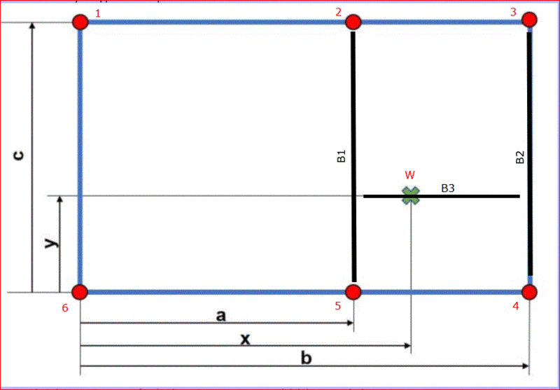
We know nothing about the "supported structure". If the load consists of a single concentrated load, the structure could consist of simple span beams B1, B2 and B3 as shown below. In that case, all reactions may be obtained using statics.
We know nothing about the load to the left of leg #2. If we did, a similar system of simple span beams could be used and again, we could easily determine reactions at each leg.

If we assume, as has been suggested in earlier posts, that the supported structure is a rigid body, then differences in elevation at bearing points need to be considered. The magnitude of reactions cannot be calculated without some idea of the supported structure and the distribution of load.

While it may be a useful exercise to determine each reaction, why does it matter? It seems more likely that all six legs would be identical rather than designing each for its particular reaction. Is that in dispute?

Capture_euepau.gif


BA
 
RB1957 said:
Why would FEA not be the tool for this job ? other than because you can simplify the problem and arrive at a reasonable (though not perfectly correct) answer without it ?

Exactly. FEA won't be perfect either for all the reasons BAR mentioned.
 
but of course all of those things will be known before you make a FEM.

Is this a wind up ?

another day in paradise, or is paradise one day closer ?
 
Just suggesting, an interesting problem has been posted and it has been asked if any methods are known that can be used to determine 6 leg reactions to a given loading condition. It is apparent that information is lacking, but proposals have been given. How about listing those KNOWN methods that COULD be used (statics, elasticity and FEA methods). Each category can be broken down. For example, within the statics category, simplified 3 leg approach, 6 leg bolt group approach (pros and cons, assumptions made)? Elasticity - springs, plates, etc. FEA - any suggestions / comments on how the task should be approached? All of the methods, if not already, can be added to the analysis toolkit!
 
have at it ! My first item would be to fully define the problem.

another day in paradise, or is paradise one day closer ?
 
Stress_Eng said:
How about listing those KNOWN methods that COULD be used (statics, elasticity and FEA methods).

Okay, let me give it a try.

Assumptions:

1. supported structure is rigid
2. attachment points are at the same elevation
3. supported structure is braced laterally to prevent translation and rotation about vertical axis.
4. each leg is fixed at the base and either pinned, fixed or rigidly attached to the structure above.
5. each leg is precisely the same length.
6. rb1957 is on holiday, far, far away. [pipe]

Calculation:

σxy = P(1/A + y/Ix + x/Iy)
where σxy is stress at eccentricity x, y from the c.g. of leg group
A, Ix and Iy are area and moment of inertia about X and Y axis respectively for the leg group.

Rn = σxy*An where R is reaction and subscript n refers to leg number.

BA
 
so now when we state all the assumptions, I think we've solved it using the method in the first reply ?
or is it load is inversely proportional to distance ^2 ?

another day in paradise, or is paradise one day closer ?
 
The only problem is the assumptions are unachievable, so the solution is wishful thinking.

EDIT: But who cares? It doesn't really matter a tinker's dam (whatever that is) what the reactions are, provided the legs are adequate to carry the worst case. When the worst case is not precisely known, engineering judgment must be used. Hopefully it is available
BA
 
What can be mentioned is that we could have numerous load cases to consider (or 1). In addition, we could also conclude that we have a possible variation in structural support conditions. By considering both load and support variations, we develop an enveloping approach (a table or matrix of cases), whilst using the same method of analysis. An example could be that we consider a case where 1 leg has failed, and 5 active. Next case, change the failed leg, and so on.
 
@Stress_Eng,

What I am envisioning from the OP's description, is six short steel columns (the "legs") carrying a structure of some kind on top. If the weight of supported structure is "W" and its c.g. lies within the rectangle enclosing the legs, the maximum reaction cannot exceed W. If the typical leg is selected to safely sustain a load of W at a specified height, that would seem to be pretty conservative and, unless W is huge, would not entail a significant cost.

The engineering cost to conduct complex calculations would far exceed any saving in material cost.

BA
 
You are absolutely right, we could just say each leg is designed to take the total load W. That would solve the problem.
 
Looks a lot like some chiller dunnage I designed not long ago. Turns out 4ft tall steel columns that are large enough to actually connect to something can carry about 17x the entire weight of the chiller by themselves, so it didn't really matter.
 
Status
Not open for further replies.

Part and Inventory Search

Sponsor