Continue to Site

Eng-Tips is the largest engineering community on the Internet

Intelligent Work Forums for Engineering Professionals

  • Congratulations GregLocock on being selected by the Eng-Tips community for having the most helpful posts in the forums last week. Way to Go!

Weight Distribution Over Six Points 6

Status
Not open for further replies.

Mernok1

New member
Dec 13, 2021
5
Hi Everyone,

I have a structure supported by six legs that are bolted to the floor. The top view of this setup is shown below. The center of gravity of this structure is marked with a green X, the fixed support legs are shown with red points. I would like to work out the force exerted on the floor by each leg.
x is bigger than a but smaller than b.
What is the best way to approach this problem?
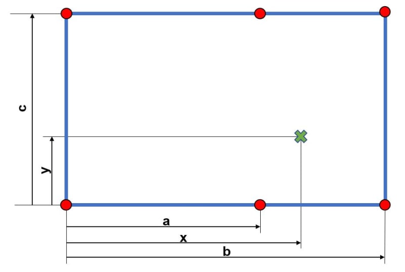
CG_c6mnnu.jpg

I have tried to derive an equation for this but as you can guess, I didn't have any luck.
I understand that I could go down on the FEA route but what I would like to get out this is an equation system that I can use in Excel when the numbers change.

Many thanks for your help.
 
Replies continue below

Recommended for you

Thanks phamENG, I imagine that would be the usual case. If we were dealing with a very heavy unit, or perhaps taller columns, it might be worthwhile to sharpen the pencil a little bit, but for most cases, this method should be sufficient.

BA
 
With what has been suggested in the numerous posts given, I would think that relevant bits of information can be extracted and used for the original problem.
 
"tinker's dam" ... the expression is "tinker's damn" ... tinkers do a lot of swearing (at least according to custom).

another day in paradise, or is paradise one day closer ?
 
rb1957 said:
Why would FEA be likely to yield unconservative results ?

Because you have to make assumptions about the rigidity of the top and the exact length of the legs, which will never reflect reality. There are literally infinite possibilities of those conditions, and no matter how many different ways you model it, there's likely one that you're going to miss.

rb1957 said:
If you want conservative results, then let each leg react "W", or "2*W", or ...

If the position of the c.g. shown is accurate, all that needs to be done for an acceptably conservative solution is to assume that legs 2,3, and 5 support the load, and calculate the reaction at 5. If the c.g. is at another location, the more general solution is to calculate the reactions assuming all possible combinations of 3 legs supporting the load, and use the largest reaction at any leg. That's just my 'brute force' approach.

Rod Smith, P.E., The artist formerly known as HotRod10
 
BridgeSmith said:
Because you have to make assumptions about the rigidity of the top and the exact length of the legs, which will never reflect reality. There are literally infinite possibilities of those conditions, and no matter how many different ways you model it, there's likely one that you're going to miss.

I don't know about "infinite possibilities", but there are many and that comment is precisely the concern.

BridgeSmith said:
If the position of the c.g. shown is accurate, all that needs to be done for an acceptably conservative solution is to assume that legs 2,3, and 5 support the load, and calculate the reaction at 5.

That assumption would lead to a conservative result, but without the cooperation of the installers, the assumption could be wrong. If they install leg 4 slightly higher than leg 3, the load is carried by 2, 4 and 5.

Even worse is if they install legs 1, 2 and 6 a little higher than 3, 4 and 5 because that puts leg 1 in tension (T1) so that legs 2 and 6 are sharing a load of T1 + W. It may even be possible to find a combination where one leg carries more than W.

BA
 
It’s interesting to hear how structures can be viewed. Aerospace structure and system components are usually certified by analysis and test. The limit load being the highest single load seen by the object in its life. In some instances an item is permitted some permanent deformation, as long as its function is not impeded. Most of the time no yielding is seen. Items are expected to sustain an ultimate load of 1.5 x limit for more than 3 seconds. Structures that have an ultimate safety factor of more than 2.5 would probably be included in a weight saving programme.
 
"It may even be possible to find a combination where one leg carries more than W." ... no, if the load is within the envelop of the reactions then the maximum reaction is equal to the load (when the load is above one of the legs). Only if the load goes outside the envelop of the reactions can a reaction exceed W.

another day in paradise, or is paradise one day closer ?
 
Another interesting aspect is manufacturing tolerances. Most drawings I see have a general tolerance of +/- 0.010” (0.25mm). Key datum features have much finer tolerances.
 
rb1957 said:
"It may even be possible to find a combination where one leg carries more than W." ... no, if the load is within the envelop of the reactions then the maximum reaction is equal to the load (when the load is above one of the legs). Only if the load goes outside the envelop of the reactions can a reaction exceed W.

If legs 1, 2 and 6 are installed a little higher than the other three, then the load is outside those three columns; and they are the only ones that matter. In a different arrangement of legs, it is possible to place three legs in a position such that one leg supports a load greater than W, even if the c.g. of load is inside the envelope of all columns.

BA
 
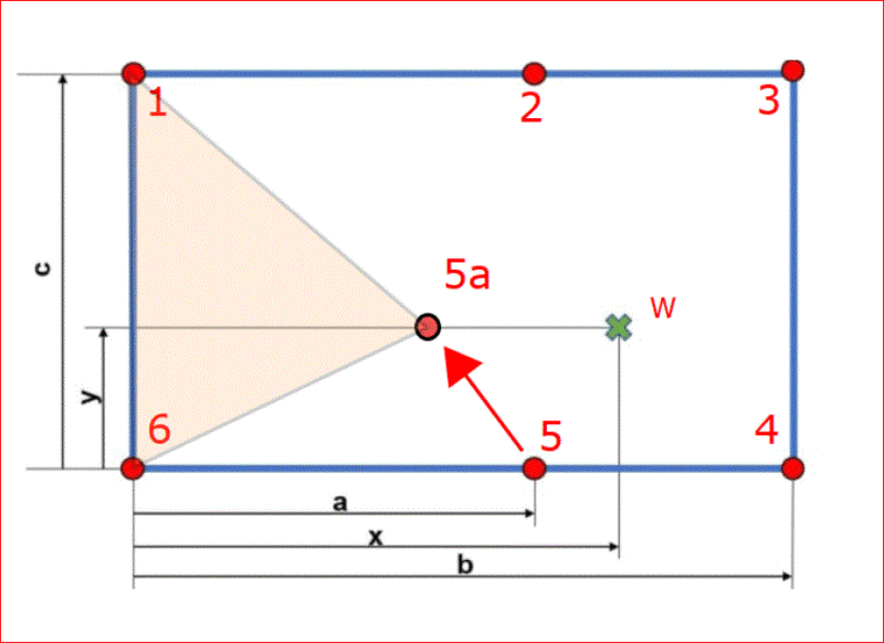
If leg 5 is moved to 5a, or a new leg is added, legs 1 and 6 will both be in tension while leg 5a will sustain a load greater than W, notwithstanding the fact that the c.g. of load is within the envelope of columns. In effect, the structure becomes a propped cantilever.

Capture_xvaj9q.gif


BA
 
Stress_Eng said:
Another interesting aspect is manufacturing tolerances. Most drawings I see have a general tolerance of +/- 0.010” (0.25mm). Key datum features have much finer tolerances.

In this thread, we have the manufacturing tolerance of the supported structure; we also have the tolerance of the column installers to consider. It is not possible to calculate reactions with any confidence whatever.

BA
 
BAretired said:
Even worse is if they install legs 1, 2 and 6 a little higher than 3, 4 and 5 because that puts leg 1 in tension (T1) so that legs 2 and 6 are sharing a load of T1 + W. It may even be possible to find a combination where one leg carries more than W.

You are correct. That is a possibility I overlooked.

rb1957 said:
"It may even be possible to find a combination where one leg carries more than W." ... no, if the load is within the envelop of the reactions then the maximum reaction is equal to the load (when the load is above one of the legs). Only if the load goes outside the envelop of the reactions can a reaction exceed W.

Incorrect. As BAretired pointed out, depending on the load location, the load on a leg could exceed 2*W. For instance, if the load is placed along the edge between 1 and 2, closer to 1, and Leg 1 is short and doesn't support any of the load, then span 2-6 becomes a back span of a cantilever.

Rod Smith, P.E., The artist formerly known as HotRod10
 
please refer to BA's assumptions
"Assumptions:

1. supported structure is rigid
2. attachment points are at the same elevation
3. supported structure is braced laterally to prevent translation and rotation about vertical axis.
4. each leg is fixed at the base and either pinned, fixed or rigidly attached to the structure above.
5. each leg is precisely the same length."

I will now apply assumption 6 ...
6. rb1957 is on holiday, far, far away.
and will not open this thread again. You guys have turned a simple problem into something unsolvable ... even when you make assumptions to make it solvable.


another day in paradise, or is paradise one day closer ?
 
Have a happy holiday, rb1957! Where to, Mexico, Hawaii, Galapagos Islands...? [pipe] [thumbsup2]

It was never a simple problem; it really is unsolvable. With assumptions, it can be made soluble, but of what value is that if the assumptions are unrealistic? Installers cannot be assumed to be magicians.

BA
 
With all of the responses given to the posted problem, it is hoped that some of the information given is helpful to the original problem. Out of all of the possible scenarios that have been highlighted, I can add just one more to the list. Here goes …
1) All detail, sub / final and the all important installation drawings are to hand. All have the required dimensional information and manufacturing / assembly tolerances, in particular those depicting interface requirements.
2) From all the drawings, calculate the following…
2a) The minimum possible final build lengths for legs 4 and 6 (to installation drawing requirements).
2b) The maximum possible final build length for leg 5 (to installation drawing requirements).
3) Assume leg 2 to be at nominal length.
3) Ignore legs 1 and 3.
4) Based on the build lengths of legs 2, 4, 5 and 6, calculate compression load on leg 5.
5) Ignoring leg 6, distribute W between legs 2, 4 and 5.
The installed structure is expected to pass final inspection. If the structure is found to be discrepant to drawing / installation requirements, a concession would need to be raised, describing all deviations. An assessment would conclude either acceptance, any alterations (repairs) or rejection.


@Stress_Eng,

In item 5) on your list, you cannot be certain that legs 2, 4 and 5 will carry any load at all. Perhaps legs 1, 3 and 6 carry all of the load.

Any three points in space describe a plane unless they are aligned, in which case they describe a line. If there are only three legs, three bearing points describe a plane. If there are six legs of slightly varying height, it is impossible to know which three will describe the highest plane. It could be 2, 4 and 5, but it could be any other combination (with the exception of 1, 2 and 3 or 3, 4 and 5 which align).

With six legs, the only possible combinations are as follows:
124, 125, 126, 134, 135, 136, 145, 146, 234, 235, 236, 245, 246, 345, 346, and 356.
If I haven't missed any, that is a total of 16 combinations. Any one of those could form the critical plane, leaving three legs unloaded in all 16 cases.

Discrepancies can occur due to (a) uneven level in bottom slab, (b) curvature of the bottom slab, (c)errors in length of leg, (d) workmanship errors by installers and (e) errors in fabrication of supported structure. Some errors may be compensating; others may not, but there will be some discrepancies.

If columns have identical mechanical properties, and each is designed to sustain a weight of W, or perhaps more, then most of them will have low axial stress. Loaded legs may share their load with others, but only after they strain enough to make contact. The strain in any column is Pn*L/AE where n refers to column number.


BA
 
Using only three columns, each reaction can be accurately calculated, even if the workmanship is not precise.

Capture_r77ah9.gif


BA
 
Status
Not open for further replies.

Part and Inventory Search

Sponsor