Continue to Site

Eng-Tips is the largest engineering community on the Internet

Intelligent Work Forums for Engineering Professionals

  • Congratulations GregLocock on being selected by the Eng-Tips community for having the most helpful posts in the forums last week. Way to Go!

Welded Nut As Datum? 3

Status
Not open for further replies.

ExpertNoob

Automotive
Dec 3, 2018
15
I am relatively new to GD&T however I have read much about it. I have an assembly that appears to be using the centerline of a welded nut as a datum for several other features on the assembly. The way the welding fixtures are designed, the weld nut is used to position the bracket. The movement of the weld nut from supplier is causing the bracket to move and weld seem to be off. I can't seem to upload my snippet of the drawing. However the bracket hole diameter is 1mm larger than the major diameter of the bolt. How can I tell if the datum is the nut or the hole in the bracket? The only thing marked on the drawing for the nut is a circle with a horizontal line through it with B1 and B2 in the lower section of the circle. The upper section is blank.
 
Replies continue below

Recommended for you

NBombardier,

How is the centre-line of the welded nut defined? There are multiple features to fixture to. Is the nut's fixtureable feature long enough to define the orientation of the centre-axis?

Are the other features fabricated after the nut is welded in place?

If the datum feature is the minor diameter of the nut, everything must be located to that. The inspector should not care where the nut's clearance hole is, unless it blocks the screw.

I would not use a welded-on feature as a datum. I would not expect any sort of accuracy out of a welded-on feature.

--
JHG
 
Those are usually used to indicate datum targets for establishing datum axis B. It is unlikely that this is a primary datum.

Typically one would distinguish between the outer surface(s) and the pitch diameter, or minor diameter, or major diameter, to use a threaded item as the basis for a datum.

You need to allow javascript to run for this website in order to upload as well as for cloudflare, which hosts the images.
 
The features that are referenced from this datum point in the drawing are assembled before, after and simultaneously to the nut bracket. What I want to do is locate off of the bracket itself for assembly so the weld seem is consistent. However I am getting resistance since the nut is a datum.
 
So studying this drawing, am I correct to say that the feature control frame is referencing Axis Datum A and the center axis of the nut has a tolerance of +/- 1mm from said axis?
 
The datums and dimensions and so forth apply to the finished product. It can be more difficult or easier to perform the operations out-of-order than suggested by the drawing, but it's not uncommon.

Also, per Y14.5, one is obligated to tell what part of a thread the datum refers to, so this drawing is incomplete.
 
NBombardier,

What drafting standard are you working to, ISO? I am trained on ASME[ ]Y14.5.

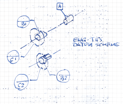
I do not see a feature for datum[ ]A. You have datum targets for datum features[ ]B and[ ]C. Your datum[ ]B fixture is a pair of pins, one round and one diamond. You have a 1mm[ ]diameter positional tolerance on the nuts. This is probably about as accurate as you can get with weld nuts. Your part will fixture differently depending on which hole gets the round pin. You would be better off if one nut were datum[ ]B, and second one datum[ ]C and the two faces datum[ ]D. I think you are over constrained.

Using inaccurate features like weld nuts, as datum features is horrible. Effectively, there are Feature Of Size (FOS) datums. YOu need things like this to be accurate.

As shown, the datum feature is the hole in your nut. You need a note stating that it is the minor diameter, since that is what can be fixtured to. Can you fixture to the holes in your bracket?

Is this your drawing, or somebody else's? If somebody else did this, I would telephone or email them, and ask what surface is used for datum[ ]B. This needs to be explicit.

--
JHG
 
This is a drawing for a new project we have recently acquired. The drawings were provided by our design group. Our fixtures were, from what I understand, designed and fabricated by an integrator. I am a manufacturing/controls engineer by trade but am educating myself on drafting as clearly nobody at my workplace understands it and it is effecting my ability to do my job. I would attach the entire print but unfortunately our customer will not allow it. I realize the print and fixtures are of poor design.

drawoh,

As for the dimensions, I originally did not understand the datum callouts. I realize now that the A datum feature is the axis of a pin on the opposite side of the assembly. This pin is assembled to the frame at the same time as the nut bracket.
I suppose my next question is does something on the print tell you the b datum is a round and diamond? On our assembly fixture, the nut bracket is currently located by TWO ROUND PINS in the nuts on our fixtures. The pins are about 1mm undersized from the minor diameter of the nut. I offered a round and diamond but think it would be better locating off of the bracket itself. The whole problem here is our welds. The bracket is moving (because nuts) and the weld is moving off seem as a result. We can not locate off of the bracket hole because it is too thin and the nut is in the way. I want to remove both pins and locate the bracket with blocks around the perimeter. From what I gather from the feedback, these nuts have a 1mm location tolerance and are not actually datums for anything. Also, I think the C1 and C2 are imaginary circles indicating we can not allow weld spatter in these areas.

 
Also, how do I know what drafting standard it is? I do not know and the print doesn't specify. I assume that would be a question for our design group.
 
NBombardier,

My drawings have a note that says something to the effect that DIMENSIONS AND TOLERANCES ARE AS PER ASME Y14.5-2009. Your drawing looks closer to an ISO standard to me. The drafting standard tells you what all the symbols and specifications mean. You need this.

I am trying to visualize how your part is fully constrained by the datum features.

Datums-20181203_bqxksx.png


This looks over-constrained to me. You could lose one of the datum[ ]targets. Also, I arbitrarily used B1 as the round pin. There is no good reason to not do it the other way. This will affect how your part is positioned in your fixture, which probably is not acceptable. This is why I proposed the alternate datum scheme, above.

An alternate fixture would be for both datum[ ]B pins to be diamond.

Regardless, your part probably cannot be installed into this fixture, unless the fixtures comes apart. Everything is being done here to assure sloppy fixturing.

Your datums features are your fixturing points. You must be able to fixture this thing to render it immobile. You must constrain three directions of translation, and three axes of rotation.

Definitely, you should call your drafter and get an explanation.

--
JHG
 
I've attached the datum feature on the other end. So datum A would be the axis of the cylinder correct? The line that passes through both of the nuts is a dimension line shown in this picture on the right (from end face of cylinder to centerline of nuts). I think I have enough info now to control the 6 degrees of freedom without using the nuts. I will get ahold of design and get some clarification also. Thanks for the help.
 
 https://files.engineering.com/getfile.aspx?folder=e4f095b5-04cf-4882-9912-20a18061722c&file=Hinge.JPG
NBombardier,

Your cylinder is your datum[ ]A feature. A long cylinder locates two translation DsOF and two rotation DsOF. All you need to do is locate along the axis, and control rotation about the axis.

Your 14mm diameter is a Feature Of Sizer (FOS) datum. Things will be way easier if this feature is accurate. Otherwise, you must make allowances for MMC/B.

If that pin is accurate, the only other constraints you need are pin[ ]B2 and one of the datum[ ]C pads.

--
JHG
 
No. It looks like a symbol substitution from using the wrong font.
 
NBombardier said:
has anyone ever seen this nomenclature? I'm referring to the two symbols that immediately precede the HOLE
That's a Chinese character means hole, the print looks like from China or Taiwan.

Season
 
In fact it is SeasonLee. It would make sense as we are a Japanese owned company. Thank you all for sharing your vast knowledge. This is a great forum.
 
Season Lee - Thanks - I was right - I had never seen that symbol! And it does look like a failed substitution, though it isn't.

Getting the right answer is more gratifying than finding I was incorrect.
 
Status
Not open for further replies.

Part and Inventory Search

Sponsor