Continue to Site

Eng-Tips is the largest engineering community on the Internet

Intelligent Work Forums for Engineering Professionals

  • Congratulations KootK on being selected by the Eng-Tips community for having the most helpful posts in the forums last week. Way to Go!

Welding on a Beam 2

Status
Not open for further replies.

JP20

Structural
Apr 7, 2020
41
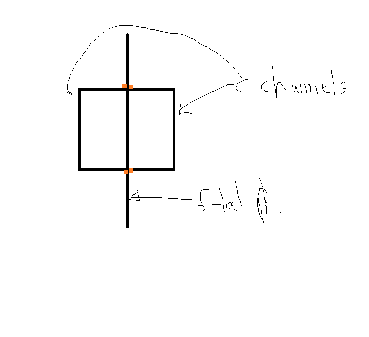
I have the below scenario: How do I resolve the force being applied to the welds given a max shear and a max moment (developed from shear-moment diagram).
The orange dots represent locations of the fillet welds. Channels are 15" deep. plate is 36" deep.
weld_ex._vtt5pe.png
 
Replies continue below

Recommended for you

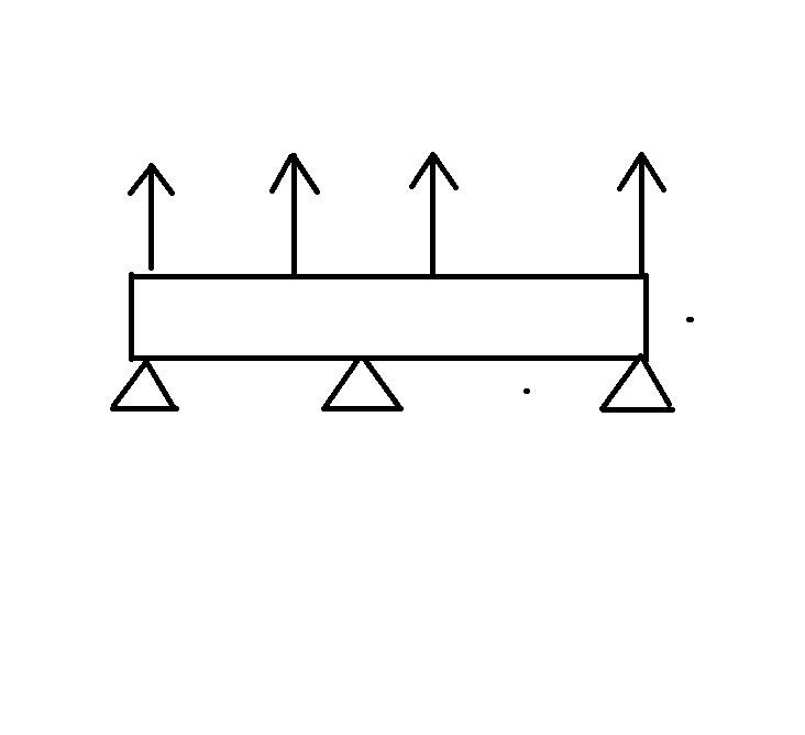
It depends on the support conditions of your beam and how the load is applied. The centroid of all your sections align, so there is no shear flow in the welds. I think you just need to deal with the local effects at the supports and where the load is applied.
 
Canpro,
If the load is being applied to the plate edge, would you have to calculate shear flow to get the load into the channels?

 
Load is being applied to the plate only. Top and bottom. Lifting device. Creating tension/bending in the plate. I am attaching the channels to the plate to prevent buckling. What I am wondering is, what, if any, loads are being applied to the welds, and if so, how can I quantify them?
 
The plate sounds really deep for a lifting device. I assume this is to resist the bending stress in the plate? Personally I would go with a conventional lifting beam that you can evaluate with standard methods and weld on gusset plates for lifting eye's.

Is there some reason you have to go with plate / channel design?
 
Ideem,

Yes we have the channels and plate readily available (on site). So, I'll need to use this configuration.
 
Follow the procedure below at your own risk:

Weld Design
1) Find properties of the built-up section, I, Q (with respect to the upper flange of the channels).
2) Compute f[sub]v[/sub] = V*Q/(I*b), in which b = t[sub]p[/sub] + 2*b[sub]f[/sub] (of channel).
3) Design the weld for the shear force V[sub]w[/sub] = f[sub]v[/sub]*A[sub]flange[/sub]


See revised, made on 3 May 20 00:36.

Use the built-up sectional properties to derive flexural resistance/capacity, and check deflection. The axial forces (P, T, V) will be resisted by the plate only .
 
JP20 - I feel your pain

Can you meet the strength requirements with the two C15's? In that case you could consider the welds as transferring the plate load to the channels like a gusset. That isn't the real case since the plate is continuous but if the plate were to buckle you would have enough weld to allow the C15's to pick up the load.

Regarding the loads, it looks like multiple slings on top. If you are using more than one crane it is likely the slings will not all pull in the same direction. I am not sure how much the slings would skew (you will have to estimate that depending on lift). But that would give some out of plane bending which would add to the C15 welds. Fortunately this would be a shear flow problem.

Do you have access to any FEA programs to see what they tell you about the load transfer from plate to C15?

Do you have Blodgetts? I am spit balling here but if you take the distance from the top of C15 to edge of plate and look at the allowable compressive load for supported-free case and then calculate the applied stress assuming section modulus is vertical plate areas outside the C15's - this might give you some idea of plate buckling on the top and bottom edge. If this works how you resolve to the C15 to plate welds I am not sure.

 
Johns201889, if the centroids align then your Q value in your shear flow calculation goes to zero (Q=a*d, d=0).

JP20, if you're using the channels resisting buckling then I would move them close to the edge of the plate that is in compression - right now your plate edge is about 8" from the channel, not sure on your plate thickness but that seems a bit far. This will also provide a bit more strength in your beam. For sizing the weld, a few things come to mind:

- You need the welds to develop any shear flow that is present
- I suspect the channel will be stitch welded to the plate - you might base the spacing of the stitch on how often the plate needs to be braced
- There might be a better approach to this, but you could base the strength of the weld on resisting 2% of the compressive force in the plate that is tributary to the stitch
- Overall beam stability comes into play, which requires you to develop your weak axis and torsional properties of the beam. Off the top of my head, I'm not sure how much of a connection you require between components to achieve for example the fully effective Iy of the section.

Typically, these kinds of welds end up being minimal. I'd be interested to see some other details here - plate thickness, length of beam, magnitude of load.
 
Canpro said:
if the centroids align then your Q value in your shear flow calculation goes to zero (Q=a*d, d=0).
Isn't "d" the distance from the centroid of the gross section to the centroid of area consider for shear flow calculations?
 
CANPRO,

I could be wrong, but isn't Q is the area above the cross section in concern, times the distance measured from centroid of the area to the neutral axis, so the maximum shear flow/stress is at the centroid of the cross section, composite or not?
 
Whether you are considering the strong axis contribution of these channels to your capacity or not, by welding them to the central plate, you are forcing this built up beam to act as a singular unit. The only way that it won't act as such, is if your welds fail, which is obviously not an allowable scenario. For that reason, you need to design these welds to carry both the strong axis and weak axis load contributions.

In order to determine how much shear will flow into the channels, you need to consider the relative stiffness of the channels to the entire built up section. Take the x axis as being horizontal in your sketch, and the y axis as being vertical. Compare your Ix of the channels to the Ix of the built up beam. Stiffness attracts load, so the channels will carry that proportion of the flexural moment.

Now that you know the proportion of the applied moment being carried by the channels, determine your limit state flexural moment for the entire beam. Now, use that value to determine the flexural moment in the channels. Take this value, divide it by the depth of the channel, and voila you have the force couple required to induce the channel moment. This is the force that your weld must resist for strong-axis loading.

For weak axis design, you can determine the shear flow as normally done for welded wide flange beams, keeping in mind that you have two welds connecting the channels (treated as flanges) to the web. I would personally design this weld to carry enough shear such that the channels can begin to yield at their extreme fibres. This ensures that your weak axis capacity will not be limited by the welds, and that a ductile failure mode can be preserved.

From experience, I anticipate that your strong axis loading will govern the design of these welds. That is, unless the proportions of the plate and channels are out of whack. Keep in mind that your strong axis capacity is going to be limited by buckling of the protruding web above the channels. You can find good references for the treatment of these protruding webs by looking up the buckling behaviour of protruding webs in T-sections.
 
Blackstar123 said:
Isn't "d" the distance from the centroid of the gross section to the centroid of area consider for shear flow calculations?

Correct, and the centroid of the area we are considering (the channel) is the aligned with the centroid of the built-up section, therefore no shear flow.

retired13 said:
I could be wrong, but isn't Q is the area above the cross section in concern, times the distance measured from centroid of the area to the neutral axis, so the maximum shear flow/stress is at the centroid of the cross section, composite or not?

My understanding is that it is the entire area of the component (the channel) multiplied by the distance from the component centroid to the centroid of the built-up section.

Think of the shear flow requirement in terms of how you build up your combined section properties. When determining your Ix of the combined section you first just lump together Ix for all individual components - you get to include Ix of the components just for showing up. After that, you apply the parallel axis theorem, which considers the distance from centroid of component to centroid of built-up section (a*d²) - this is where you start to get the most benefit of a built-up section (ie adding flanges to a vertical plate instead of just stacking plates together vertically). But, in order to develop this added benefit in the section (a*d²), you need to ensure the components are adequately fastened together to act as a unit (shear flow, a*d).

In this scenario, since the all of the centroids align, we only get to add our Ix values together, no added benefit from offsetting the channels, and zero shear flow.

Craig_H said:
In order to determine how much shear will flow into the channels, you need to consider the relative stiffness of the channels to the entire built up section. Take the x axis as being horizontal in your sketch, and the y axis as being vertical. Compare your Ix of the channels to the Ix of the built up beam. Stiffness attracts load, so the channels will carry that proportion of the flexural moment.

Now that you know the proportion of the applied moment being carried by the channels, determine your limit state flexural moment for the entire beam. Now, use that value to determine the flexural moment in the channels. Take this value, divide it by the depth of the channel, and voila you have the force couple required to induce the channel moment. This is the force that your weld must resist for strong-axis loading.

I respectfully disagree with this statement. I agree with your first statement regarding the channel taking load in proportion to the stiffness (channel load = Ix channel / (Ix plate + 2*Ix channel). Once you determine the percentage of the load the channel is taking, the weld simply has to deliver that proportion of load to the channel - flexural stress in the channel doesn't come into play, and this is not the same thing as shear flow. In fact, for a simply supported beam with a UDL your maximum shear flow occurs where the flexural stress is zero.

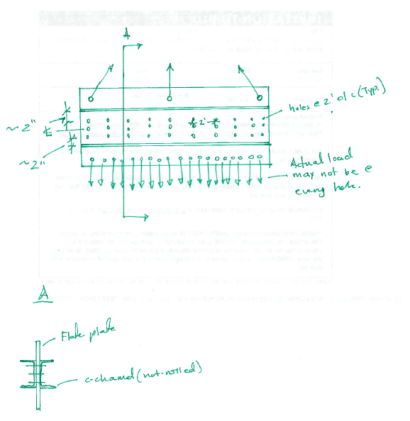
JD20, I didn't see that this is part of your other thread. You had a nice sketch of the beam in that thread that would have been good to include here (I've included it below).

COMPOSITE_BEAM_a9bphs_sqy68a.png


There might be (probably is) a more rational way to approach this, but I would be inclined to take 2% of the your strong axis moment, apply it as a weak axis moment, and design your welds accordingly. As Craig_H pointed out, your channels will take some of the load based on their stiffness, and that load will have to get transferred into the channel along its length and then back into the plate near the support points.
 
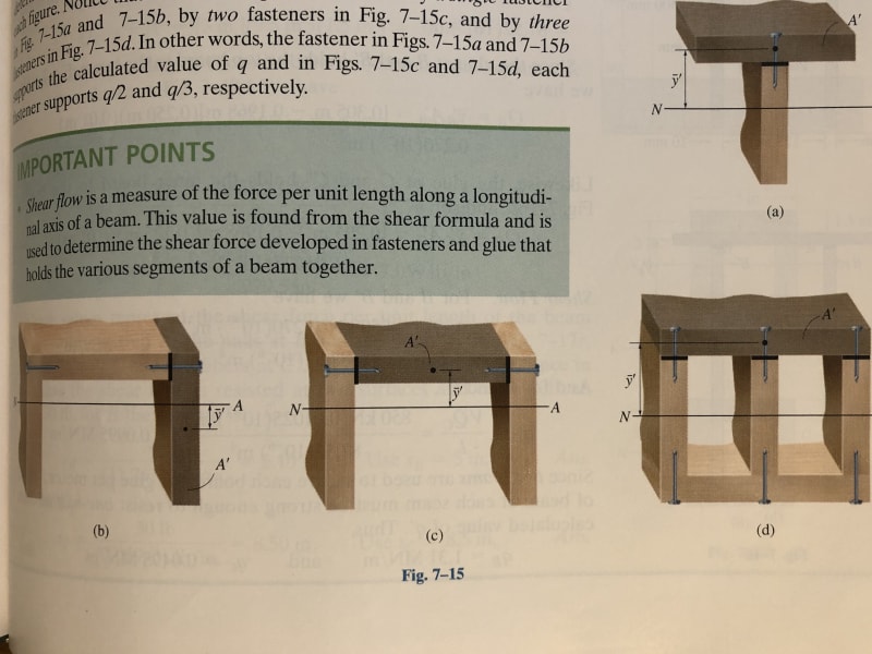
retired13, none of those examples show the component in question crossing the NA. The illustration looked familiar, it’s the same as my mechanics of materials book (Hibbeler), but I have an additional figure. See below, figure (b).

81EFD81B-9921-400B-AC92-ED124B6BF761_gdafpk.jpg
 
CANPRO,

Interesting. How about case (c). Actually, I don't think about component, but treat all parts togather as a single unit, then decide the location needs to be investigated/connected. Simple check is that, for a rectangular shape, the maximum shear is at the mid-section, where A[sub]top[/sub] & A[sub]bot[/sub] are maximum. Anyway, it just provided for your information.
 
Now I realize (b) demonstrates the case with the centroid of the leg is offset from the NA of the built-up section, thus, Q=A'*y'. If centroid coincident with NA, we can't use take this short cut, or this method, then we need to use (c), if the location shown is the interest. But does not mean shear flow is zero. Find an example for square built-up section, you will know what I mean.
 
In seeking to further understand this quote:
CANPRO said:
Once you determine the percentage of the load the channel is taking, the weld simply has to deliver that proportion of load to the channel - flexural stress in the channel doesn't come into play, and this is not the same thing as shear flow. In fact, for a simply supported beam with a UDL your maximum shear flow occurs where the flexural stress is zero.

I am curious what "load" you see being transfered between the central web plate and the side channels? To me, in order to ensure continuity of the cross-section, the flexural stress where the web and channel meet must be the same. Hence, the welds must be able to engage tension and compression in the channel flanges, thereby inducing a continuity of flexural stress. The welds cannot transfer much vertical shear due to the obvious geometry of the channels.

I think we are in agreement that shear flow is zero in strong axis flexure, and due to the low magnitude of weak axis loads, will likely not govern there either.
 
Grag H,

Bending produces compression and tension stresses in the cross section, and the stress is zero at the NA. IMO, I don't consider compressive and tensile stress (flexural stresses) are the same as shear flow (stress). There is shear flow at the junction of the center plate and the channels, as well as flexural stress. The weld needs to satisfy both.
 
Status
Not open for further replies.

Part and Inventory Search

Sponsor