Eng-Tips is the largest engineering community on the Internet

Intelligent Work Forums for Engineering Professionals

What Prevents Inadvertent Stress Concentrations or Crack Initiation on most prints? 7

Status
Not open for further replies.

SBlackBeard

Aerospace
Apr 21, 2022
12
0
0
US
I'm a designer - there is a recurring theme with some parts we've seen recently, where there is a sharp step right where we'd least want one. We battle with other departments - they say it meets the print, we say it doesn't.

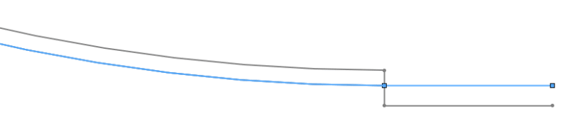
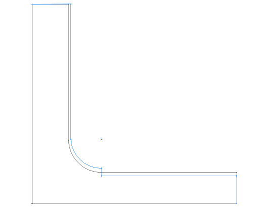
For example, we might design a bracket with a fillet/blend specifically to avoid a sharp internal corner for stress reasons, but we control the size of the radius or the adjacent flat surfaces with a profile tolerance - say .015 (we use inches). I realize this allows for considerable surface variation (like they draw in the GD&T books!), but we also have a block tolerance surface finish of 63 or 125. Here's an image of it (blue is as-built, grey is as designed):
goes_bump_in_the_night_qlts4v.png


You can see there is a step near the root of the fillet. Likely, this was machined with two different tools or from two directions, so I understand HOW it happens. At prior jobs, quality would have rejected or reworked the part. At the current job, Quality says "because the step is within the surface profile tolerance, it meets print."

I originally thought block tolerance surface finish of 125 Ra should cover it. I then thought maybe we should say this is a controlled radius, but we see steps at the tangency point. The more I consider it, our surface finish should call out an Rmax that prevents this. I'm particularly concerned if this happens on aluminum parts prone to fatigue.

How do other people control for this type of manufacturing artifact with the print?
 
Replies continue below

Recommended for you

Fire the company that makes parts like that. That works as it is at least a workmanship problem, but I see where QA/QC would weasel on the profile tolerance.

I guess you could try "NO STEP CUTS" allowed, but it is certainly outside the surface roughness requirement.
 
1. Try to specify "non-uniform" profile zone (see picture).

2. If your shop still try to justify abrupt changes within the tolerance zone, the "per unit" control is not only for straightness / flatness:

Capture1_hyxemm.png


"For every expert there is an equal and opposite expert"
Arthur C. Clarke Profiles of the future

 
SBlackBeard,

I would argue that your step is a feature you did not specify, therefore you reject the part.

In a court of law, your vendor may be able to prove his part meets your specifications. Don't deal with that vendor ever again.

--
JHG
 
Out side diameters and adjacent shoulders it is very simple to turn the radius, and adjacent shoulder. Where it get difficult is inside diameters and adjacent shoulders.
Where on a single tool can be used leaving no step.
In an id if there is no clearance it may require two or more tools and a step may be unavoidable. I suggest in such cases a .005 max step on all surfaces. Excuse the typing ol cell phone.
 
When milling steps are unavoidable and have to be smoothed out by hand. Requiring hand blend. And is time consuming and expensive.
So only add no steps allowed when absolutely necessary.
 
To make it clear to inspect and not be interpreted wrong make it clear no steps allowed or .005 max step permitted.
So this is clear and concise.
 
Thanks for all the replies.

@3DDave and others - I have little/no control over firing a vendor. I could make a stink on some parts and ask for "return-to-vendor" that would maybe start to hurt a vendor's score card, but it's hard when Quality is saying "what's the violation?"

@ many - I could put "no steps" - but I'd be adding this note to every print with a fillet. Then the next scratch on the print would make me put "no scratches" in the notes. Then the swirl, then the ding, then the yadada... It seems like big OEMs should have it figured out how to prevent a stress riser in radiused brackets and shafts. But maybe this is still the way to go.

@drawoh - yes, I agree, surface finish was my go-to, but I think the standard block tolerance uses Ra as 125 - letter 'a' below. My thought was that maybe I could put an Rmax of .0002 on the print? That would be where letter 'b' is below, so I'd have to change block tolerances or add a new note.
surface_finish_g8lrpy.png


@SDETERS - I'd thought that too, but this step is really at the tangency point. How do you specify the quality of an implied tangency?

I feel like I just want to write a nasty-gram to Quality and the Vendor, but I'd rather make a change to all my prints in the future that is defensible and parts don't get here that I need to argue about. So far, Rmax or "No steps" are the leading candidates. Appreciate the opinions, keep them coming!
 
If we fire every supplier that made a part that complies with the drawing yet doesn't meet your expectation, we would have no suppliers left.

SBlackBeard said:
Quality says "because the step is within the surface profile tolerance, it meets print."
This is 100% correct.
The question of "What's the violation?" is 100% valid. This is a drawing issue, not a supplier issue. You are correct to strive to fix the drawing rather than strive to fix the supplier. Everybody wants craftsmanship but nobody wants to pay for it, so being specific about the part requirement on the drawing is crucial. I've seen some good suggestions with other responses. CR is one possibility. Controlling the radius with profile on a per unit basis is another possibility. Something as simple as the note that was suggested is a good one too.

SBlackBeard said:
We battle with other departments - they say it meets the print, we say it doesn't.
Why do you say it doesn't? What part of the drawing is being violated?

SBlackBeard said:
...but I'd rather make a change to all my prints in the future that is defensible and parts don't get here that I need to argue about.
THIS RIGHT HERE!!!

Keep your supplier and fix the print. If they can't meet your newly stated requirement then a supplier change is in order.


John Acosta, GDTP Senior Level
Manufacturing Engineering Tech
 
powerhound - I see the value in your specific suggestion on dealing with this. I'll put that note on drawings from now on. That fix you suggest is brilliant and should be a chapter all its own in the next revision.
 
3DDave, TheTick, powerhound - thanks for the replies.

I looked at this case in more detail, because it did seem like surface finish wasn't met... even though block tolerances call out Ra and not Rmax.

Working in theory and general terms is nice, but this specific one had a .003" step.
step_height_d65az2.png

I drew it with the fillet, but it likely works about the same assuming it's flat.

In a spreadsheet I wrote out the deviation as .003 for 8 lines (arbitrary) and .000 for 12 lines. The average value is .0012. Ra is the average of the absolute value of the difference between the average and the actual for each line. So a step of .003 minus average of .0012 = .0018 for the first 8 lines, then for the next 12 lines, the absolute value of .000-.0012 = .0012. The average then equals (8*.0018+12*.0012)/20 = .001226 or an Ra of 1226 microinches. I did this again assuming it was a ramp from 0-.003 across the first 8 lines (.0009/.0012/.00015/.../.003) and then .000 for the next 12... that's an Ra of 806 microinches. I then dialed down the step height until the Ra calc equaled 125 microinches - you'd have to have a ramp of 0-.0004" or a step function of .00026 to meet an Ra of ~125. Even if you play with the number of lines that contribute, the answer stays in that ball park. If 19/20 lines are .00026 and one is 0, Ra is 153 microinches. If 1/20 lines is .00026 and the rest are .000, the Ra is 107. Anyway, not sure everyone will follow that but the summary is that it looks like if you were to swipe a profilometer across any step that is a few tenths high, you'd fail surface profile requirements, even when they are expressed as an Ra and not Rmax. I'll see if I can validate this with an actual profilometer and a .0005 feeler gauge.

I don't have time right now, but the next step will be to dig into what the stress analysis answer would be.

BTW, My intent is not to come up with a mountain of data and storm in waving it in someone's face - my intent is to figure out "what's right" - if stress folks don't care on certain parts, then let the vendor do what they need to. If a step like this is a big deal for stress on other parts, I'd prefer to find a clean and defensible way to state it on the print.

Thanks for the continued input.
 
Dave,
I'm not at all surprised by your response. I knew it was coming but didn't really care. The reason is because most of your responses over the years have been hard nosed and angry. I don't know why you have that attitude but your "specific suggestion" of firing the supplier lines up with it perfectly.

John Acosta, GDTP Senior Level
Manufacturing Engineering Tech
 
Your response is expected. No value added to the original problem, just attacking those who point it out. Pandering to the incompetent suppliers that make their problems the problems of engineers to guess just how they will do the damage and require thousand page documents to cover every possible way they can screw up.

Had one like that - engineering in my company decided the supplier had a flow chart to follow of excuses. The supplier decided not to passivate stainless parts (per the drawing,) which showed up in the fog-chamber test as rust. Their response: Fog chamber must be contaminated. Spent many hours on outside testing to prove that wasn't the case. Then it went to salt-fog. Rusted up like a furry caterpillar. Their excuse: they used a special anti-corrosion treatment, but just missed this one part. That treatment? Overnight oil for use in machining parts. It went on and on. We specified sealed bearings - they "sealed" them with grease. The best one was a gear driven synchro. The assembler took the item from their packaging and the gear fell off. They said it was mishandled. We checked the rest and the supposedly press fit gear (designed to spec not to dimensional drawings, so their design responsibility) was loose on all of them. Because by that time we demanded that the housings were passivated. So they had pried the gears off, and put them back on. Loose. So their excuse: we didn't specify an axial retention force. Sure - we specified that they survive a 30 g impact load, but just 1G was too much.

I'm tired of watching people do crap work and make crap excuses. If you prefer to cover for the incompetence of others that's certainly yours to do, but it does erode the industry - it's an acid that cuts and destroys and putting up with poor performance and excuses hurts everyone.

 
Here's how a reasonable company deals with a defect like that:
Company: Is that step a problem?
Engineer: Yes, it is.
Company: We will re-work the parts to remove that step.
Engineer: Great. What can I put on the drawing to tell you not to allow a step?
Company: We use a general note "NO STEPS LARGER THAN THE SURFACE FINISH ALLOWED."
Engineer: OK - then we'll do that.

(Actual outcome)

New design goes to another company and they ask why that note is on the drawing when surface roughness covers it. The engineer shrugs and the other company guy says "You were buying from XYZ, weren't you?" The engineer says they cannot comment. Both laugh.

When the response from a company is - We. Don't. Care. About. You. that's a reason to fire them. When the part they made is one they would reject if they were buying parts for their own use but want you to pay. That's a reason to fire them. When they refuse to offer an answer about how to avoid this and the procurer has to wander into the wastelands looking for a solution to this one supplier problem. That's a reason to fire them. When that part, in fatigue sensitive aluminum, has a stress riser that might crack and ultimately kill someone and they act like this. That's a reason to fire them. Did the company call and inform that their process would create a step in that location and ask if that was suitable before accepting the contract? If not, that's a reason to fire them.
 
To your first response: If passivation was on the drawing and they ignored that requirement, that's indefensible. They didn't do what the drawing said to do. I'm not arguing about that. Bad on them.

To your second response to me which deals with the OP: that's a drawing change that was actually one of your suggestions that I mentioned was a good one in my first post on this thread (albeit not to the value you recommend). As far as surface roughness being sufficient to prevent that step goes, according to ASME B46.1-2009 [1-1.2], that step is only considered a flaw if it has been agreed upon in advance by the the supplier and customer. In the absence of that agreement, it's not a flaw so rejection of the part shouldn't be based that as long as everything else is within the specified tolerance zone. It's likely that B46 is not actually invoked on the drawing though so nothing actually locks in, by default, the step being controlled by the surface roughness. The other thing to consider is that since Ra is an average, the step can actually be larger than 125 and by how much depends on the condition of the rest of the surface.

Regarding the last paragraph of your second post to me: I agree with everything in it. Is that actually the case here though? Did any of that actually happen? Is the severity of this flaw such that a failure will cost lives? Maybe this is just a cosmetic issue.

And finally, I wasn't attacking you. I just think it's a bad idea to fire suppliers who make parts that comply with the requirements they are given. If you participate in a forum like this, you can't be so deeply offended when someone doesn't agree with you. In my opinion, adding the note you suggested is sufficient but not to 125 microinches. Now inspection will reject any part that has a step larger than .000125". That doesn't seem to make sense to me if this is just a cosmetic feature.

John Acosta, GDTP Senior Level
 
Status
Not open for further replies.
Back
Top