SBlackBeard
Aerospace
- Apr 21, 2022
- 13
I'm a designer - there is a recurring theme with some parts we've seen recently, where there is a sharp step right where we'd least want one. We battle with other departments - they say it meets the print, we say it doesn't.
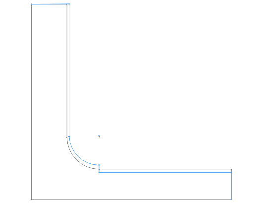
For example, we might design a bracket with a fillet/blend specifically to avoid a sharp internal corner for stress reasons, but we control the size of the radius or the adjacent flat surfaces with a profile tolerance - say .015 (we use inches). I realize this allows for considerable surface variation (like they draw in the GD&T books!), but we also have a block tolerance surface finish of 63 or 125. Here's an image of it (blue is as-built, grey is as designed):

You can see there is a step near the root of the fillet. Likely, this was machined with two different tools or from two directions, so I understand HOW it happens. At prior jobs, quality would have rejected or reworked the part. At the current job, Quality says "because the step is within the surface profile tolerance, it meets print."
I originally thought block tolerance surface finish of 125 Ra should cover it. I then thought maybe we should say this is a controlled radius, but we see steps at the tangency point. The more I consider it, our surface finish should call out an Rmax that prevents this. I'm particularly concerned if this happens on aluminum parts prone to fatigue.
How do other people control for this type of manufacturing artifact with the print?
For example, we might design a bracket with a fillet/blend specifically to avoid a sharp internal corner for stress reasons, but we control the size of the radius or the adjacent flat surfaces with a profile tolerance - say .015 (we use inches). I realize this allows for considerable surface variation (like they draw in the GD&T books!), but we also have a block tolerance surface finish of 63 or 125. Here's an image of it (blue is as-built, grey is as designed):

You can see there is a step near the root of the fillet. Likely, this was machined with two different tools or from two directions, so I understand HOW it happens. At prior jobs, quality would have rejected or reworked the part. At the current job, Quality says "because the step is within the surface profile tolerance, it meets print."
I originally thought block tolerance surface finish of 125 Ra should cover it. I then thought maybe we should say this is a controlled radius, but we see steps at the tangency point. The more I consider it, our surface finish should call out an Rmax that prevents this. I'm particularly concerned if this happens on aluminum parts prone to fatigue.
How do other people control for this type of manufacturing artifact with the print?


