Eng-Tips is the largest engineering community on the Internet

Intelligent Work Forums for Engineering Professionals

What Prevents Inadvertent Stress Concentrations or Crack Initiation on most prints? 7

Status
Not open for further replies.

SBlackBeard

Aerospace
Apr 21, 2022
12
0
0
US
I'm a designer - there is a recurring theme with some parts we've seen recently, where there is a sharp step right where we'd least want one. We battle with other departments - they say it meets the print, we say it doesn't.

For example, we might design a bracket with a fillet/blend specifically to avoid a sharp internal corner for stress reasons, but we control the size of the radius or the adjacent flat surfaces with a profile tolerance - say .015 (we use inches). I realize this allows for considerable surface variation (like they draw in the GD&T books!), but we also have a block tolerance surface finish of 63 or 125. Here's an image of it (blue is as-built, grey is as designed):
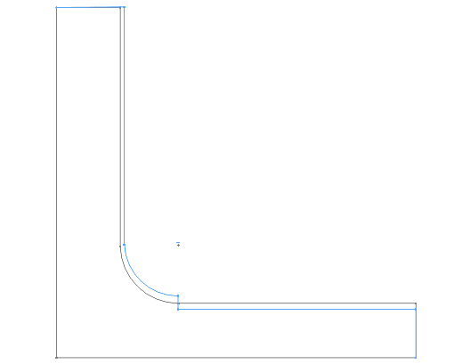
goes_bump_in_the_night_qlts4v.png


You can see there is a step near the root of the fillet. Likely, this was machined with two different tools or from two directions, so I understand HOW it happens. At prior jobs, quality would have rejected or reworked the part. At the current job, Quality says "because the step is within the surface profile tolerance, it meets print."

I originally thought block tolerance surface finish of 125 Ra should cover it. I then thought maybe we should say this is a controlled radius, but we see steps at the tangency point. The more I consider it, our surface finish should call out an Rmax that prevents this. I'm particularly concerned if this happens on aluminum parts prone to fatigue.

How do other people control for this type of manufacturing artifact with the print?
 
Replies continue below

Recommended for you

3D,
Simultaneity between the features inside a specific pattern considered by itself is not a simultaneous requirement. Simultaneous requirement is about simultaneity and basic relationship between the tolerance zones of different geometric tolerances applied to different features or patterns, where the unifying factor between them is the common datum references in the same order and same boundary conditions. Simultaneous requirement is not a synonym to a pattern, although it is one type of pattern. Why do you fail to differentiate between simultaneity the word and simultaneous requirement as a defined concept?
 
3D said:
It still doesn't solve the continuity problem unless they are simultaneous and then it does so by making the part much more expensive than it might have to be.

This was addressed, but I'll try one more time.
If two features such as a radius and a planar feature are designed tangent, and are controlled by what even you would consider as separate requirements, such as profile tolerances referencing different datum references. On an actual part produced according to the design, can you tell where one tolerance zone starts and another one ends?
There is no way to know for sure where the limit is, and the controls can slightly overlap. A measured surface ends as far as the last sampled point on it is located.
Now if there is a step between the radius and the surface, is it reasonable to say, "hey that step is exactly the limit between the radius and the planar feature that I was looking for, therefore it is not part of any of them! Let it be, and both features comply". That's not reasonable. The step is not even supposed to be there, why let it govern where the inspection of the radius ends
 
Section 4.9 of 2009 says the lower segments of a composite FCF are not a simultaneous requirement. Is that what we’re talking about here? That shouldn’t even be a question. I think I missed part of this.

John Acosta, GDTP Senior Level
 
powerhound,
I mentioned this, but the counterargument that I get here is that there is still "simultaneity" within the pattern for the lower segment when considered by itself.
But that is not a "simultaneous requirement" per the definition of the concept. It may look like a fussy differentiation, but the lack of it is exactly what leads to the "null datum feature reference" misunderstanding and interpreting separate profile tolerances without datum references as imposing mutual relationship requirements.
 
That's great and it greatly restricts the remainder of the surface in ways that are often not required. As I pointed out - you can use that very expensive approach, but it is still very expensive because it controls not just transitions, but everywhere a larger tolerance was allowable, even if you don't feel that applying to all surfaces means at the same time.
 
3D, it may not be more expensive than what they are willing to spend to prevent the problem.
It depends on the maximum size of the step they would allow and whether the entire part must be inspected for it or if it applies locally where the risk is.
If applied as a general tolerance on an individual basis for UOS surfaces it can be used to limit relatively large steps.
If a tight control is required they can apply it locally, as I mentioned.
 
B said:
It was widely discussed in the industry and therefore brought to the attention of the committee at multiple occasions.

Do you attend the committee meetings and have first hand knowledge? The attendees aren't supposed to discuss the meeting contents.

I was looking at where you suggested limited areas. You tend to make a wall of text and bury whatever is important in a bunch of copy-paste.
 
"If this is too costly or troublesome, the control could be applied directly in the drawing views only to some features that are at risk of stress concentration or where irregularities need to be tightly controlled from any other reason."

This was part of short post, 29 Apr 22 19:56.

Do you think the committee is isolated from the rest of the industry or introduces changes based on a single change file?
 
3DDave said:
I recall a President of the US arguing about what "is" meant. You could have backed his argument.

Sarcasm aside, but it is you who were preaching in a recent thread1103-494217 that dimensioning and tolerancing is like a programming language. What you wrote there could lead someone to believe that you are aware of the importance of knowing how to encode something precisely to get the expected outcome. It is not consistent with your tendency to mix between spoken language associations and defined terms. Simultaneous requirement has a specific defined meaning, you aren't supposed to relate everything you associate with the word simultaneity to it, interpreting unintended patterns from a drawing or thinking that you specified one when you didn't do so. I bet you are one of those who used to specify symmetry where position is appropriate because "the feature has to be symmetric to the datum".
 
Burunduk,

I glanced through the responses between you and Dave and didn’t see what I’m about to say. Simultaneous requirements is a way of invoking a pattern. Another way of doing that is by stating the number of instances (i.e., 3X, 5X, etc.). That number stated with the composite FCF makes the holes a pattern. That pattern has to comply with all segments. The 5X—or whatever it is—keeps them a pattern, nothing about the DRF in the lower segments do. I know you know this but maybe the words “pattern” and “simultaneity” are more different than we think.

John Acosta, GDTP Senior Level
 
powerhound,
You are absolutely correct.
This is why I have been saying repeatedly that controlling surfaces separately by profile tolerances without datum references or the number of places indicated does not impose a simultaneous requirement between them or any other type of pattern. It is essentially a form control that applies separately to each surface, to limit among other things the step the OP is concerned about.

There would be no simultaneous requirement or any sort of pattern that connects the tolerance zones, since the profile tolerance in the note would not include datum references to impose a simultaneous requirement (per section 4 of Y14.5-2009) and so none of the following would apply: "nX, n COAXIAL HOLES, ALL OVER, A ↔ B, n SURFACES, simultaneous requirements, or INDICATED" to create a pattern per the section 1 definition (note the plural in "SURFACES").

I also argued that if there is a pattern invoked by nX or the other methods and no datum references are specified for the features in the pattern, it doesn't mean that there is a simultaneous requirement invoked by the "null datum reference". A pattern can be a pattern without being a simultaneous requirement (the low segment is an example of a pattern not in a simultaneous requirement, even when datum references are used). I asked a question - how many degrees of freedom does the "null datum reference" constrain? Still didn't get an answer to that.
 
Burunduk,

Could you point me to the place in any Y14 standard (or ISO - honestly curious if they have handled it rigorously) where it is clearly defined what happens where two adjacent/tangent tolerance zones meet?

I ask because I've found its something the standard lacks in clarity, however you seem to be very sure about it being obvious what happens at these transition points, especially points of tangency, or at the very least a non-issue.

I'm not sure I follow your logic. Hoping you can expand on it a bit.

The tangency line is only there in theory. On a real part, if it's made to print, the best you could have is some narrow border zone, not precisely defined in any way, where one surface blends into another. This zone can be considered as part of both surfaces, and points on this zone could be inspected as part of the control of one surface, or the other, or both. So if there is a step right between the radius and one of the planar surfaces on the part, it could be detected and treated as a violation of either the profile tolerance of the radius or the profile tolerance of the planar surface.
 
chez311, it's a good question.
The strongest support for this would be common sense and some experience.
If you ever measured parts, even on a basic optical comparator, you could have seen that for tangent surfaces under great magnification it is very difficult to tell one feature ends the other one starts. You don't have those nice looking lines that are there on the model. Does it mean that violations can fall between the cracks? In my opinion - it's the contrary. 

Here's why,
The Fundamental Rules paragraph section in Y14.5-'18 states "UOS, all tolerances and datum features apply for full depth, length, and width of the feature" (and a similar rule was in the previous versions). It is mandatory that the tolerance zone covers the entire as produced feature. So when you can't tell exactly where that depth/length/width ends, and you detect an irregularity of the surface approximately where the limit might be, you have no reason to assume you are no longer in the tolerance zone of the feature you are inspecting, or not yet at the tolerance zone of the next feature - one of the zones should surely reject a violation larger than both tolerance zones. 

More support for this can be found in the recently published standard, ASME Y14.45. The draft version from July 2020 defines what a measured surface is:  "measured surface: a collection of all measured points of a feature that separates the feature from another feature or from free space." 
In other words, what separates an inspected feature from another feature is the last point you choose to measure on it. If the violation happens to be on the border, why let it escape the measurement, especially since you can't tell for sure where the border lies.
 
you detect an irregularity of the surface approximately where the limit might be, you have no reason to assume you are no longer in the tolerance zone of the feature you are inspecting

what separates an inspected feature from another feature is the last point you choose to measure on it. If the violation happens to be on the border, why let it escape the measurement

These are qualitative evaluations, not quantitative ones. It only confirms what my experience has been, that measurements in these border regions - especially points of tangency - are lacking a rigorous definition without supplementary documentation, and typically are unfortunately left up to the inspector to muddle through.
 
chez311,
It may be so, and possibly if nothing is unusual, with adequate transition between the features, this area might not get any special attention.
But if an irregularity is clearly detected, (otherwise there would be no issue and this thread wouldn't exist) can't the specified tolerances on both surfaces justify a rejection? Practically speaking could the vendor claim the step is not covered by any of the tolerance zones and that the part is compliant to the drawing? Or would it force him to adjust his process to avoid the step?
 
Hi All,

Sorry I'm late joining this thread - you guys have gone very deeply into patterns and simultaneous requirements. I've been even deeper into this rabbit hole myself for several years. I remember the Dallas meetings in 2016 that powerhound mentioned - there was definitely a lot of discussion of the "more than one datumless FCF" case.

I'll start by acknowledging that Y14.5 doesn't explicitly address the issue of whether or not two (or more) datumless Position or Profile FCF's qualify as a simultaneous requirement. There are two camps - one saying that there would be a simultaneous requirement and the other saying that there would be separate requirements. However, after examining the evidence and following the consequences of each interpretation, I concluded that the hypothesis that datumless FCF's are separate requirements is far more defensible and consistent with the content of the Y14.5 standard. I basically agree with what powerhound and Burunduk said in their latest posts.

Evan Janeshewski

Axymetrix Quality Engineering Inc.
 
If the topic regarding the numbers 0 and 1 for datum feature reference count was discussed and left unresolved then a pox on both their houses.

If the datum reference frame is that important in order of evaluation then it should be the left hand portion of the feature control frame to indicate that the features cannot be evaluated for any characteristic without datum references.

I think the term "pattern" needs to go. They are related features and may be randomly located during the design process. Per the convention use it can only apply to identical elements in some uniform arrangement - therefore excluding a profile and position tolerance as "pattern".

What I really want to know is why '2018 was so rushed. On the typical schedule it should not have been until 2022 or later; if on the official schedule it was about a year early after previous allowance for procrastination. 2016 must have been the last meaningful input before closing all discussion other than - "This is what we are doing; vote for it" in 2017.
 
Status
Not open for further replies.
Back
Top