Eng-Tips is the largest engineering community on the Internet

Intelligent Work Forums for Engineering Professionals

Which CAD was used to design Stratolaunch?

Status
Not open for further replies.

PrintScaffold

Mechanical
Sep 8, 2006
453
0
0
RU
Very impressive! Does anybody know which CAD did they use? Was it NX, CATIA, or something else?
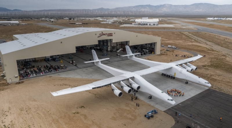
stratolaunch-rollout_kykesx.jpg


Replies continue below

Recommended for you

JNieman said:
Solidworks and other "middle of the road" CAD packages have come a long way since I last worked with them several years back. They have been incorporating a lot more freeform surfacing tools, flow and thermal analysis, and some FEA tools. I have not used any such tools. I was just surprised to learn of it. It's possibly just something that makes 'pretty pictures' that will make minor/less-critical design work "look better" or make pretty pictures for advertising materials that make them look like a more advanced/competent engineering team... or maybe it's pretty legit. I dunno. The people I know using Solidworks use more established CAE tools.

I use both Solidworks and Catia extensively- the difference between the two is much, much narrower than it was 10 years ago.

When you go to Catia, you get that last 5% of capability with surfacing. I would say that any surface that you could create in Catia, you could also create in Solidworks, but the process, level of accuracy attainable, and number of iterations/amount of time required to get to your final shape with good underlying math is bigger in Solidworks.

As far as CAE, I use Solidworks' native analysis package a fair bit for stress and strain analysis, as well as for mold flow checks- and it's perfectly functional as a first pass solver. On simple stress/strain problems, in my experience, Solidworks results and ANSYS results always agree. What Solidworks doesn't handle well is more complicated problems- collisions, flexible parts, parts with nonlinear characteristics, very large dynamic assemblies, etc. So for 95% or so of CAD users, Solidworks provides all they will ever need.

In the aerospace world (which I'm not a part of) it almost certainly isn't enough on its own.
 
You guys must be joking. Any CAD package I know of, in sufficiently incompetent hands, could have generated that fuselage profile.

It looks like one continuous nasty loft, from bow to stern done by some junior-designer hired 1 week after the into course.
The fwd fuse corner fillet and the wing "fairing" blend look terrible. Maybe there was some need to compromise, for unseen internal issues.
The tail will have interference drag at the root. More than if it looked more like the marketing promo models.
Reality probably bit somebody on the a**, and this is just what they settled for.


STF
 
Regarding the flat sides. They need a big ground clearance for the payload, therefore the height of the fuselage is given. But it is not worthy to make its width similar, thus getting closer to the cylindrical cross-sections. That would mean extra material and weight for nothing in return. Having said that, I am not an aerospace engineer.

There were some interesting comments suggesting inexperience of the designers. A honest question (I do not live in US) - is it possible in US that someone inexperienced is hired to do such kind of job? If yes, what is the reason? Is it because all experienced aerospace designers would not want to leave their good jobs for some dodgy startup or what?

 
Greg ,
Getting rid of the inboard Part of the tail plane would put a massive bending load on the end of the tail cone when full up or down elevator was applied.
B.E.

You are judged not by what you know, but by what you can do.
 
The fuse shape isn't that dissimilar to the B52 (except where they sweep it up to lift the wing) which makes sense as it is also is largely unpressurized.

The critical horizontal tailplane loads would likely be quite asymmetrical already, given those three engines appear to be very closely spaced by airliner standards. Will be interesting to see how much tail shake it has during a full power ground run.
 
You guys crack me up. This plane was designed by one of the most experienced and recognized aircraft designers on the planet, Burt Rutan. Google him. If you have followed aircraft design for any length of time you have heard his name, and his company Scaled Composites, mentioned in connection with all the most innovative and record-breaking designs of the last 20 years. If there is anyone more capable of designing an aircraft for a single purpose mission, I don't know who it would be. This plane was not designed for high production volume or peak efficiency. It is intended to safely transport rocket vehicles to a specified launch altitude.
 
No, Jboggs, that doesn't matter.

They spent untold hours of thorough design time, but these guys looked over the skin shape for DOZENS of minutes. DOZENS. Obviously they know enough to dictate the appropriate modifications. [bigsmile]

(tongue firmly in cheek, folks, don't take it seriously)
 
PrintScaffold said:
There were some interesting comments suggesting inexperience of the designers. A honest question (I do not live in US) - is it possible in US that someone inexperienced is hired to do such kind of job? If yes, what is the reason? Is it because all experienced aerospace designers would not want to leave their good jobs for some dodgy startup or what?

For a project of this scale, budget and visibility it is HIGHLY doubtful than anyone even remotely green would be hired to design something like this. The comments of the posters above who know more about who is and isn't an experienced designer make it clear that the designer of this plane is not a new kid on the block.

The other factor is that regardless of Burt Rutan's experience designing aircraft, it's highly doubtful he was the one spending a couple thousand hours in Solidworks creating surfaces- but I would imagine someone like that doesn't just hire CAD operators off the street. I'm sure that the people creating the math for these shapes were highly experienced.
 
Not to mention that the people willing to risk years and years of investment, and millions of dollars of product (satellites and business ventures) have to feel comfortable using their aircraft. It doesn't matter how 'cheap' you make a craft if no one wants to risk their payload riding along. Let's be practical here.
 
My humorous comments were taken too seriously. I will clarify.
I have admired Burt Rutan for a long time, having watched his career for decades after seeing my first Long-EZ, walking around a Beech Starship, following the Virgin Atlantic's course as it flew, and cheering on the SS1 project.

This aircraft bears NONE of the characteristics of a Burt Rutan design.


STF
 
Maybe not Burt himself, but someone who is in Burt's immediate group. It lacks the sleekness that most of Burt's designs had, but it does have the functional approach that he so often used. Or the guy Brains, from the Thunderbirds.
 
In my opinion it has more Rutan features than you might imagine. First the 100% composite construction. The very high aspect ratio wings. The split fuselage. The long skinny features. True, Rutan is known for canard wings, but there's a lot more than that here. And don't forget, you're looking at only half of a complete design. This carrier aircraft exists for one purpose - to carry the rocket vehicle that isn't even shown. Not many folks have designed two separate aircraft that are intended to function as one.
 
Status
Not open for further replies.
Back
Top