Eng-Tips is the largest engineering community on the Internet

Intelligent Work Forums for Engineering Professionals

  • Congratulations waross on being selected by the Tek-Tips community for having the most helpful posts in the forums last week. Way to Go!

Which stress to use in Strand7 to verify results using Roark's Formulas

Status
Not open for further replies.

BendingMoment123

Structural
Apr 1, 2020
25
0
0
ZA
Hi, I just want to verify my stress results in my plate segments in Strand7 using Roark's formula. Should I use the surface (either -Z or +Z in terms of the plate's local axes. In this case the top of the plate is the -Z surface), or mid surface calculated stresses. So you would have either a mid surface stress in the global xx,yy and zz directions, and you would have -Z surface stress calculated in the global xx, yy and zz directions.

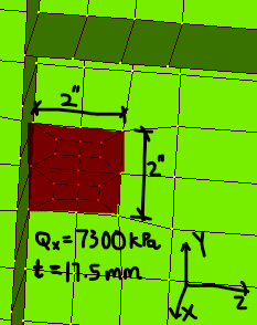
Note that the dark green plates are stiffeners welded to the surface of the light green plate. I just want to check a portion of the light green plate, which I have highlighted in red below. The highlighted portion has a uniform pressure applied over it of 7300 kPa. The plate dimensions are 2" X 2" (50.8 mm X 50.8 mm) and is 17.5 mm thick. What edge support configuration would you assume as well?

Screenshot_2022-04-11_121114_nithui.png
 
Replies continue below

Recommended for you

If you treat that little dark area as an isolated plate with Roark's formulas, I don't think there's any way to get a meaningful result.
Generally, if deflections are small, you're concerned with bending stresses which are maximum at the plate surfaces.
If deflections are large, you'll also develop tension/compression/shear stresses at the mid-surface.
I'm not familiar with the software in question, but it may or may not actually calculate those mid-surface stresses.
 
Deflections are small. So I assumed the left end of the highlighted region as fixed (where the stiffener is) and all other edges as simply supported. The max stress at the center of the fixed edge using Roark's was 31 MPa. I used the surface stress in Strand (not mid surface) and got a stress of 36 MPa at that center node, which is kind of close.
 
You cannot use plate formulas to accurately analyze a small section of what appears to be a web plate attached to stiffeners. Any similarity to classical solutions should be taken with a grain of salt, even though the boundary conditions (clamped at stiffener, pinned (free to rotate) elsewhere) are not completely unreasonable.

I am curious about the loading. What causes 7300 kPa acting on a 5x5 cm^2 part of a plate?
 
Ok, thank you. The pressure is from the impact force of the diverted gate in the chute. The force from the diverter gate is 18.82 kN. The force is exerted over a bump pad of dimensions 2x2 inches.
 
How did you model the impact? A linear elastic static analysis will not capture impact (specifically if the impact is very fast) properly. You should include inertia, model the impact as a dynamic load (pressure as e.g., a step function or triangular increase-decrease) and probably also model metal plasticity (nonlinear material) to arrive at physically correct results.
 
Bendingmoment. What jurisdiction are you working in? I note Strand7 is common in Aus but less common elsewhere. More information about what your trying to achieve might be useful.
 
Status
Not open for further replies.
Back
Top