Continue to Site

Eng-Tips is the largest engineering community on the Internet

Intelligent Work Forums for Engineering Professionals

  • Congratulations KootK on being selected by the Eng-Tips community for having the most helpful posts in the forums last week. Way to Go!

Why doesn't shear-friction apply when reinforcing is in compression? 2

Status
Not open for further replies.

DTS419

Structural
Jun 21, 2006
162
ACI 318-14 R22.9.4.3 says that shear friction does not apply when the reinforcing is angled so that it would be in compression and that as a rebuilt, Vn=0. This is counterintuitive as by inspection, the reinforcing angled up against the applied shear would be better. Why is Vn = 0 when the reinforcing is angled upward, and how would you determine the strength of this connection if in fact you had a case where the reinforcing was angled upward?
 
Replies continue below

Recommended for you

Shear friction depends on clamping the concrete together. When the reinforcing is oriented such that it would tend to separate the concrete contact surfaces that are supposed to be clamped under shear slip the approach is, understandably, invalidated. This doesn't mean that you then have no shear capacity. It just means that you'll have to get your shear capacity some other way. And that way may well involve moving shear about using the very angled bar that's neutered your shear friction play.
 
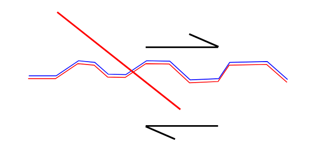
Here's a physical explanation that makes more sense to me. Imagine you have a surface with aggregate interlock and a bar oriented opposite of the shear friction:

Shear_Friction_1_ergkap.png


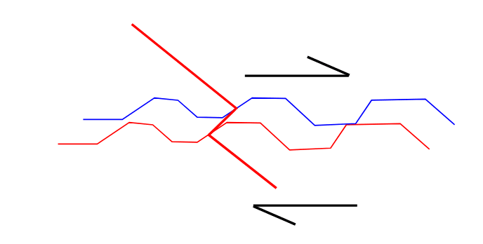
Once the shear is applies, the interlocked aggregate will try to slide over each other therefore moving out and toward the direction of shear:

Shear_Friction_2_fhaevq.png


That is bending the bar, not really stretching it. Keep in mind that my image is greatly exaggerated - if you let the wall slide enough, it would stretch, but not until it got into the geometrically nonlinear range)

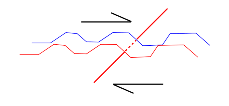
If it was oriented the other way, the bar would stretch along its axis:

Shear_Friction_3_rtkjju.png


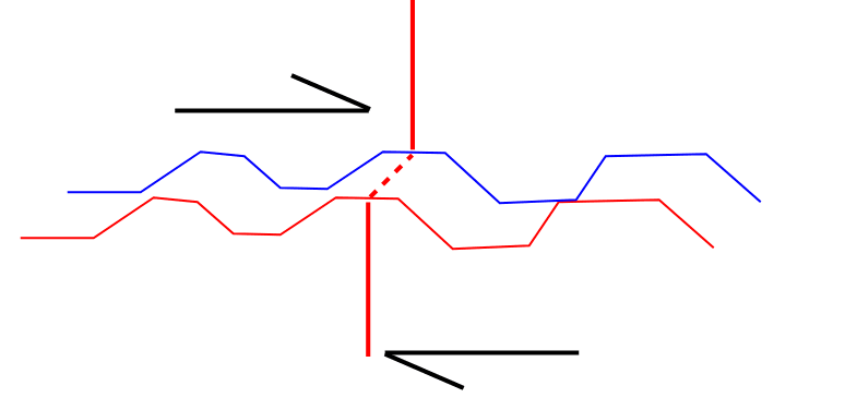
And with a perpendicular bar, you would have a combination of bending across its axis (along the sliding interface) and stretching along its axis (perpendicular to the sliding interface):

Shear_Friction_4_zulwwj.png


There may be some amount of resistance from dowel action, but there isn't that classic shear friction bar stretch
 
So how would you calculate the shear strength of a connection where the reinforcing was angled to be in compression if Vn due to shear-friction is zero?
 
I think that it's time to show us a sketch of your situation.
 
I think it's a limitation in that the testing for this situation does not exist. Have you read the commentary on shear friction and some of the background research yet?

To me it's like the limitations on perforated shear walls in wood construction, it's to constrain usage to the zone of similarly tested assemblies.
 
The actual shear capacity would be some combination of the friction against the surface (due to the weight, not due to the clamping effect of the bars), and the dowel action of the bars (considering them to be shear dowels rather than tension members). Depending on the application and/or the jurisdiction, you may or may not be able to count on those. Friction due to weight often isn't allowed to be considered, and the shear dowel action may require a lot of movement prior to engaging, and the two certainly shouldn't be combined (at least not using a static friction coefficient).

I don't think the limitation is necessarily because a lack of testing, but rather because the two sources of potential restraint aren't the best.
 
For a sketch of my situation, see ACI 318-14 Fig. R22.9.4.3b - that is exactly my situation.

I get the shear-friction method is based on the premise that resisting tension in the steel creates a theoretical clamping force so that without tension, you wouldn't have a clamping force and therefore no shear-friction. But if we step from the theoretical into reality for a moment, someone with no engineering background could intuitively recognize that angling the bars upward against the shear force would be better than if they were at 90 degrees or worse, sloped downward in the direction of the shear.

If ACI shear-friction can't be used here, it seems to me that simply considering the shear strength of the bars as if they were bolts would be sufficient.
 
DTS419 said:
But if we step from the theoretical into reality for a moment, someone with no engineering background could intuitively recognize that angling the bars upward against the shear force would be better than if they were at 90 degrees or worse, sloped downward in the direction of the shear.

What do you mean by this? Are you saying that because something is intuitive, there shouldn't be equations to represent it? Or are you suggesting the equations are wrong, and that the orientation in Figure R22.9.4.3b should have more shear capacity than if the bars were oriented as in Figure R22.9.4.3a or perpendicular?
 
chris3eb said:
What do you mean by this? Are you saying that because something is intuitive, there shouldn't be equations to represent it? Or are you suggesting the equations are wrong, and that the orientation in Figure R22.9.4.3b should have more shear capacity than if the bars were oriented as in Figure R22.9.4.3a or perpendicular?

I'm simply saying that it's counterintuitive that Vn=0 when the bars are angled against the applied shear force.
 
Compression in the rebar means the rebar is pushing back at the concrete on either side of the joint. I.E. its making a tendency to separate the joint. Whereas if tension is developed in the rebar due to the shear, then the rebar is restraining the crack from opening.
 
dL said:
Compression in the rebar means the rebar is pushing back at the concrete on either side of the joint. I.E. its making a tendency to separate the joint. Whereas if tension is developed in the rebar due to the shear, then the rebar is restraining the crack from opening.

Well put. E_steel = 29,000 ksi. E_concrete = ~4,000 ksi. So I'd imagine what the code writers were envisioning was that the compression in the steel would be reducing the effective normal force across the joint which is required for aggregate interlock. Not to say aggregate interlock goes away completely but I guess they don't recognize any equations that would capture this effect.
 
There is little wonder that ‘shear friction theory’ is little understood. When it was developed, it was based solely on testing. The simple equations developed at that time were said to include the effects of clamping, friction of roughened surfaces, and dowel action. No ratios of these components were proposed. Although more research has been done since, I think the queries on this forum illustrate there is work to be done. There was, for obvious reasons, a rush to accept the theory, but the story is not finished.
 
So, any other thoughts on how one might go about computing the shear strength of this situation (dowel bar angled against the applied shear)?
 
DTS419 said:
So, any other thoughts on how one might go about computing the shear strength of this situation (dowel bar angled against the applied shear)?

This comes back to my previous request that you show us a sketch of what you're up to here.

DTS419 said:
For a sketch of my situation, see ACI 318-14 Fig. R22.9.4.3b - that is exactly my situation.

That's of no use in this regard. We all have the kindergarten level shear friction diagrams from ACI committed to memory. What we need to be able to help you solve your real problem is the real context of your actual situation:

1) Is this a cold joint or a monolithic joint?

2) Is this a construction joint in a beam? A slab to shear wall connection? A topping being made composite?

3) What other forces dominate this connection concurrently with the shear being considered?

4) How has it come about that you have angled rebar at this joint? That, in it self, is a bit of a rarity.

You've got some very sharp people contributing to your thread and they'll know a lot of interesting tricks. But most of those tricks will be context dependent and you're unlikely to hear about them without supplying the context necessary for folks to be able to offer you creative solutions.

The "push back" that dL mentioned speaks precisely to a possibility that I mentioned at the top:

KootK said:
And that way may well involve moving shear about using the very angled bar that's neutered your shear friction play.

The push back is, itself, a shear resistance mechanism. Just not a shear friction shear resisting mechanism. The trouble with it is ensuring that any shear absorbed by the angled dowels in compression has somewhere viable to go further down the line. It probably doesn't but, until we know the broader context of your problem, there's no way to know.

We're all busy professionals and I understand that posting a sketch eats up valuable / billable time. It is simply a functional truth that high quality responses often require a high quality "ask". You pay to play.
 
Status
Not open for further replies.

Part and Inventory Search

Sponsor