Eng-Tips is the largest engineering community on the Internet

Intelligent Work Forums for Engineering Professionals

Will this orientation of cylinder/slides have excessive wear?

Status
Not open for further replies.

MechvsManu

Mechanical
Mar 20, 2024
24
0
1
CA
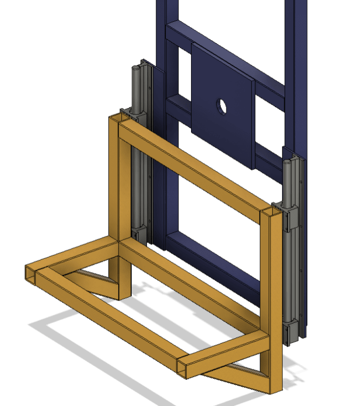
This is a lifter I have designed to lift 1000lbs. This is one side and is mirrored on the other side. The cylinder is capable of 700lbs.
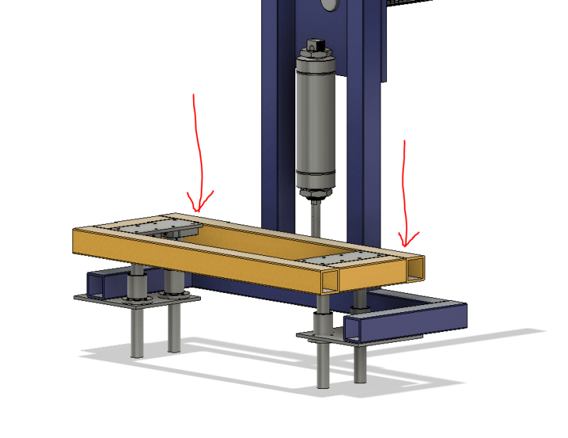
Will the cylinder being off and not centered between the linear shafts/bearings have an issue with lifting?

Also would it help if I did 2 cylinders in the location of the red arrows over one larger cylinder in the center? Or would that cause a binding issue?
I'm clamping against an upper frame so I don't need the cylinders to lift exactly simultaneously.

I don't have space to mount the cylinder under and centered due to clearance issues.

Concept_se4tza.png
 
Replies continue below

Recommended for you

probably a lot depends on the cg of the 1000 lb load, and how stiff the support frame is. do some hand calcs for deflection of the support frame under load.
 
The question is whether your linear slides can absorb the moment load of the vertical applied force being off-center from the center of gravity of the load. If the cylinder is installed properly (with ball-jointed or otherwise pivoted/hinged connections) so that it cannot carry any of this moment load and cannot be bound up due to inevitable misalignment, the cylinder won't care.
 
MechvsManu said:
Good point. The blue frame is tied to the other side with 2x3 HSS tubing. Deflection is negligible.
1000lb on a cantilevered sq tube frame, deflection is probly more than you think. If this is a several thousand dollar professionally built machine with tight tolerances that can keep itself aligned as Brian suggested then yes it may work. Some DIY home project with cheap guides and weld alignments +/- 2 deg, I would find a different way to support it.


My plan is to waterjet a steel plate that holds the Flange-Mounted Shaft Supports and rod ends for the cylinder. This plate will be welded to the tube frame (by a Red Seal welder).
The Flange-Mounted Linear Ball Bearing's would be placed and bolted to a plate with oversized holes to allow for alignment.

We're clamping a 2x4 frame with sheathing so it's a pretty stiff, evenly weighted, body.
 
Are there two lifting cylinders and eight guide rods and bushings - I don't understand your section cut and symmetry? You are going to fight with alignment on that. Also, if there are two cylinders you will have an issue with even lifting and skewing which will bind the guide rods. One guide rod completely constrained and then some amount of misalignment float in x and y for the others would be good.
 
With only one bearing per rod, the system will definitely bind.

One bearing is not enough to constrain rotation. At least two bearings (spaced reasonably far apart) on a linear guide are always used. Though, if you put 2 bearings on each rod, the system will be over-constrained so you'd have to machine it all pretty precisely to get the required parallelism/perpendicularity, or, as an alternative to using 2 bearings per rod, use some minimum constraint design concepts.
 
Will it wear? YES!!
Will it bind? Probably.

If the center of the lifting force does not pass directly through the center of mass of the load, a moment is created. Linear bearings can withstand significant transverse (side) loads, but they are NOT designed to withstand significant moment loads.

Having multiple linear bearings in parallel (as in your image) does nothing to relieve the situation. However, having two linear bearings in series on the same shaft DOES absorb a greater moment load. And the farther apart they are the greater moment load they can withstand.

Picture it this way: how does a linear bearing resist a moment load, a twisting load, on the shaft? The moment load actually creates a matched set of equal and opposite concentrated point reaction forces at each end of bearing contact. These are not distributed loads along the length of the bearing. They are concentrated at points at each end of contact. So, moving those two contact points apart actually decreases those reaction forces. The best way to separate those points of contact is to have more than one bearing on the shaft.


I've changed the way I'm lifting now. This is preliminary but my plan it to put a tierod cylinder at each end next to the shaft. These bearings are good for 1000lbs each, it's a 6" lift with a 24" shaft. I believe this will stop any bending load.

What do you think of this iteration?

Screenshot_2024-03-21_061913_hc1gfa.png
 
Much better.

Though, by the looks of it, you seem to have a welded structure without any machining afterwards (maybe it just seems that way because the model is not complete), and you likely won't get good straightness / flatness / perpendicularity on those surfaces. General practice is to machine the surfaces where the bearings and rails are mounted.
Though, instinctually, based on proportions of the whole thing, that might not even be a problem in your case.

The alternative is to use a linear guide system that is less sensitive, i.e. requires lesser accuracy, for example wheel-in-profile systems (e.g. Winkel, HevyRail).
 
Much better... but...

As far as the cylinders are concerned, you have two options. My preference would be one cylinder centered between the bearings. But if you go with two cylinders, find some way to synchronize their action. It is possible (but difficult) to synchronize hydraulic cylinders. But synchronizing pneumatic cylinders is not feasible at all. One is ALWAYS going to exert a little more force than the other due to internal friction variations.

One common way to achieve synchronization is to tie the motion of the two sides together with something like a torsion rod with rack and pinion on each end (or roller chains). Mechanical synchronization also eliminates the effects of any friction variations in your linear bearings too.
 
Jboggs said:
One common way to achieve synchronization is to tie the motion of the two sides together with something like a torsion rod with rack and pinion on each end (or roller chains). Mechanical synchronization also eliminates the effects of any friction variations in your linear bearings too.

I've used a pair of cylinders in plenty of similar situations. Synchronization is generally not a concern if the structure being lifted is rigid enough (OP's structure seems to be), the length of pneumatic hoses going from the valve to each cylinder is approximately the same, and W/H ratio is reasonably low (W being the distance between two linear rails, and H being the distance between two bearings on the same rail).

OP seems to have long enough H, and not too wide of a W. I wouldn't expect the lack of synchronization to be a problem here.
 
1. get alignment couplings for the cylinder rods - 2. if one of the linear bearing assemblies is fully constrained and the other bearing assembly can float some there does not need to be any precision alignment. Do you need more than 1/16" (1.5mm) accuracy? If not, consider something with more clearance for the floating side? You might be able to get by with a linear bearing assembly on one side and looser-fitting uhmw guides on the opposite side or maybe eccentric cam followers set to provide clearance. You can induce a lot of load in your cylinders by forcing the frame to deflect to accommodate non-parallel linear bearings.
 
dvd (Mechanical) 1. get alignment couplings for the cylinder rods - [URL unfurl="true" said:
https://www.mcmaster.com/products/air-cylinder-rod...[/URL]
2. if one of the linear bearing assemblies is fully constrained and the other bearing assembly can float some there does not need to be any precision alignment. Do you need more than 1/16" (1.5mm) accuracy? If not, consider something with more clearance for the floating side? You might be able to get by with a linear bearing assembly on one side and looser-fitting uhmw guides on the opposite side or maybe eccentric cam followers set to provide clearance. You can induce a lot of load in your cylinders by forcing the frame to deflect to accommodate non-parallel linear bearings.]

I've never used alignment couplings before, thanks for the link.
The linear bearings have a 1° misalignment capability. I feel like a waterjet plate (shown below) should be plenty to make sure everything is aligned properly. The plate is welded to the 2x2 steel frame for support but all mounting points are precision cut. When I figure out the cylinders they'll be mounted to this plate too.

The setup is basically a clamp to lift an 8ftx8ft 2x4 box. It should be super ridged and not really have flex anywhere due to the construction.

Do you still think I need to make one side floating?

Screenshot_2024-03-21_141349_h26pse.png
Screenshot_2024-03-21_141540_lhkfss.png
 
A precisely waterjet-cut plate with rails mounted parallel won't help if the bearing blocks are not held accurately, so I still think that allowing for a looser mounting on one side will help. From what I see of your assembly, it looks like you don't need that much precision - the box doesn't have that much precision.
 
This whole thing does what after the box is lifted?

There are a whole bunch of failure modes with the cylinders, hoses and controls that might allow one or both sides to lower unexpectedly.

You should probably have a fail-safe mechanical latch in the lifted position. Especially if this whole thing is used to lift and transport the box.
 

Good point. I'll make the far side floating. Thanks for the advice.
Also precision isn't an issue with this setup. The box itself is not going to be square as you said.
 
Status
Not open for further replies.
Back
Top