Continue to Site

Eng-Tips is the largest engineering community on the Internet

Intelligent Work Forums for Engineering Professionals

  • Congratulations SSS148 on being selected by the Eng-Tips community for having the most helpful posts in the forums last week. Way to Go!

Wind Envelope Procedure with a Half Hip Roof and Dutch Gable

Status
Not open for further replies.

medeek

Structural
Mar 16, 2013
1,104
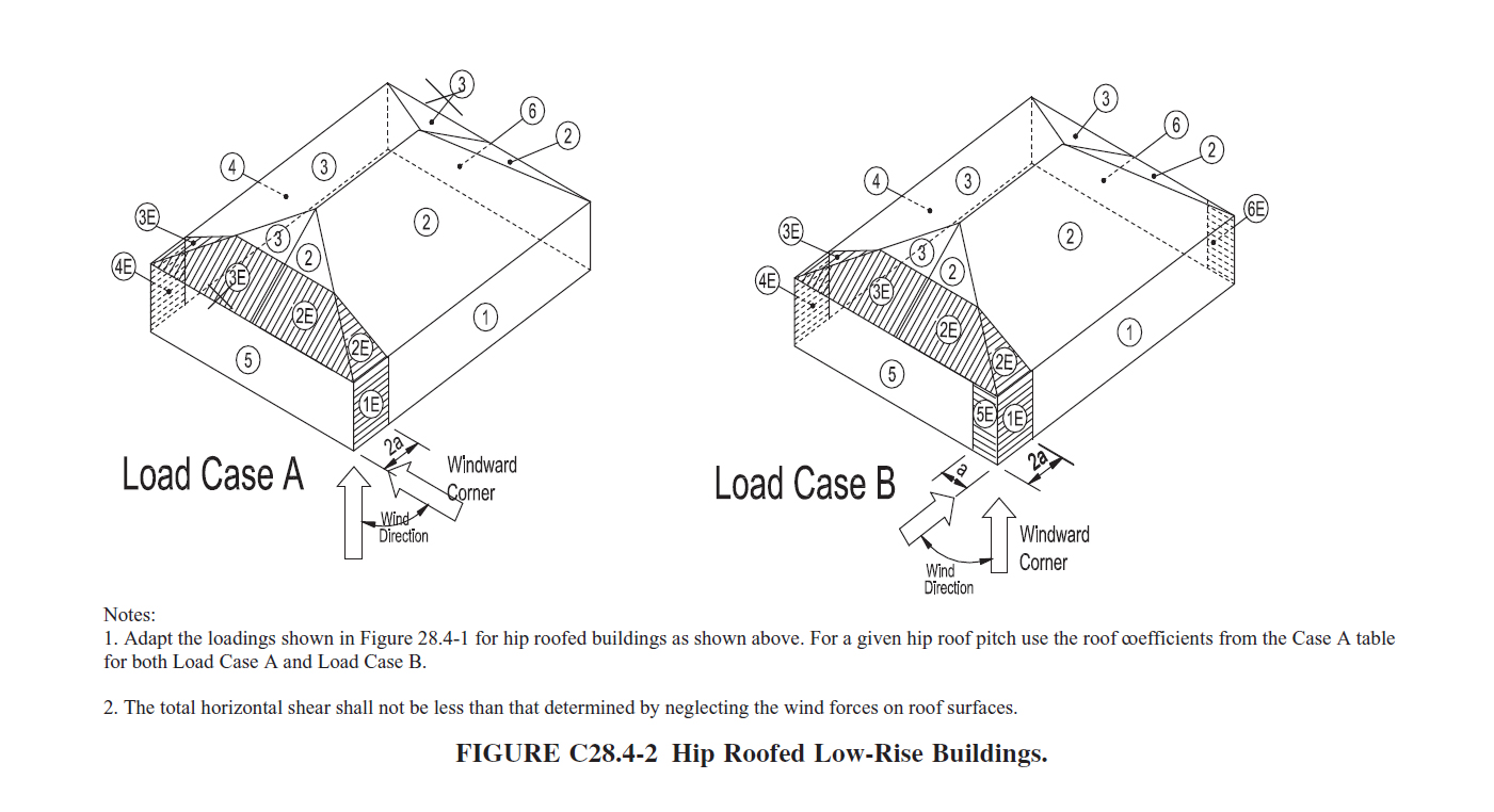
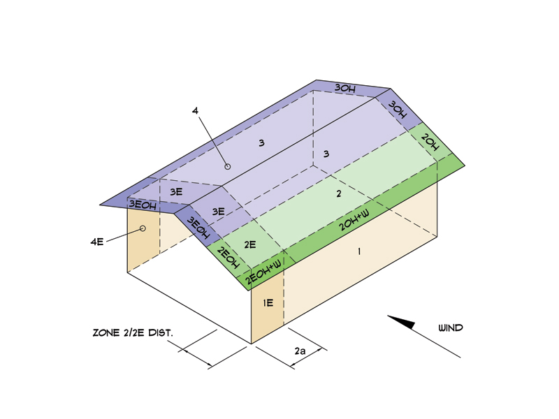
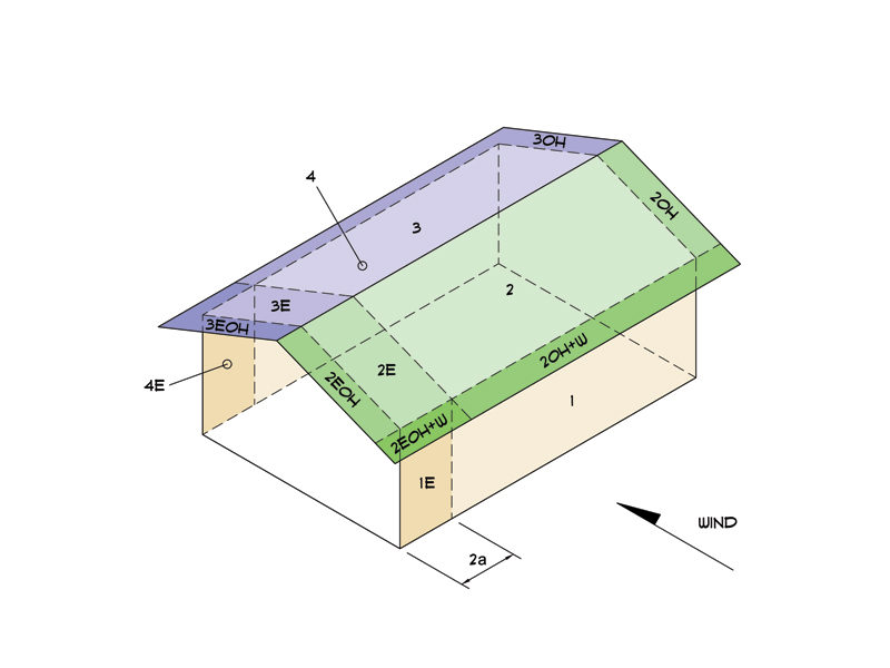
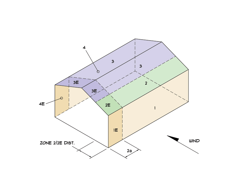
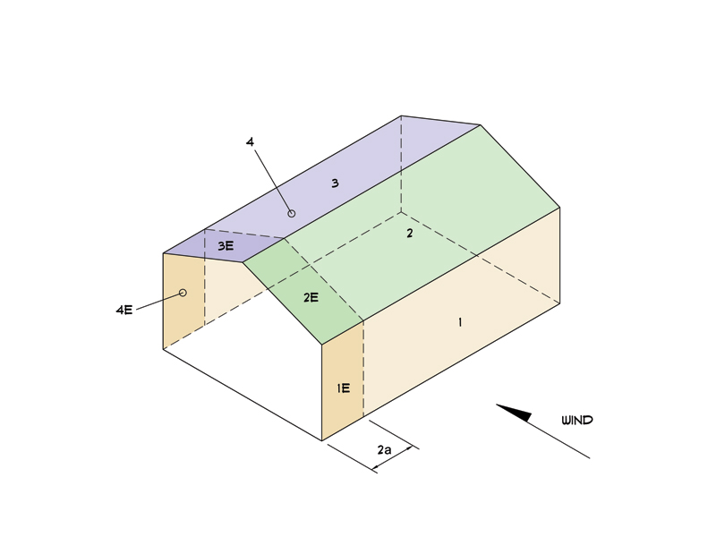
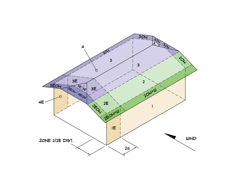
As I started plowing into the programming of my new web based MFWRS wind load calculator I decided to try and pick up as many roof types as possible. I'm intending to use the Envelope Procedure from Part 1 of Ch. 28 of the ASCE 7-10 so things are a bit limited with respect to building aspect ratio, height etc... Section 28.2 specifically states that one can use this method to analyze buildings that have gable, hip and flat roofs.

My question is can this method also be used to analyze Half Hip and Dutch Gable roofs which are essentially somewhere in between a Gable and Hip type roofs? Rationally it makes sense to me but just thought I might throw it out to the crowd for any comments or corrections.

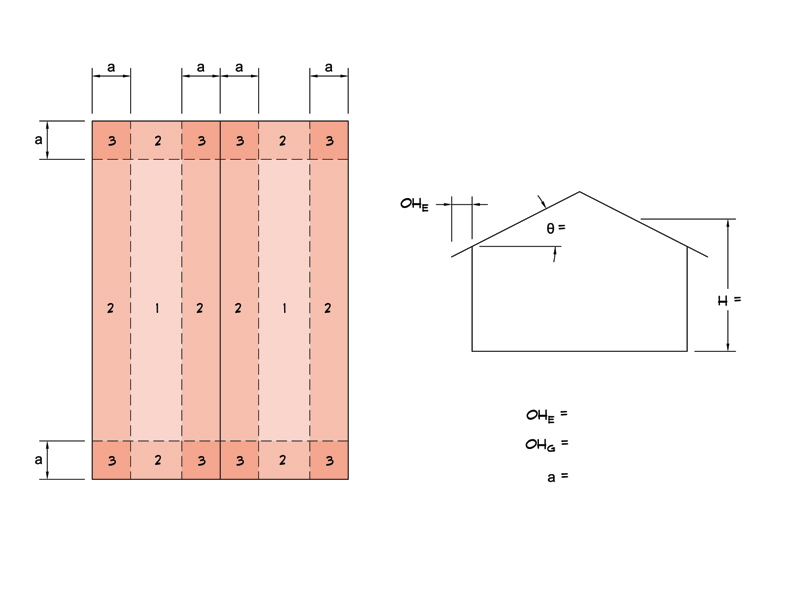
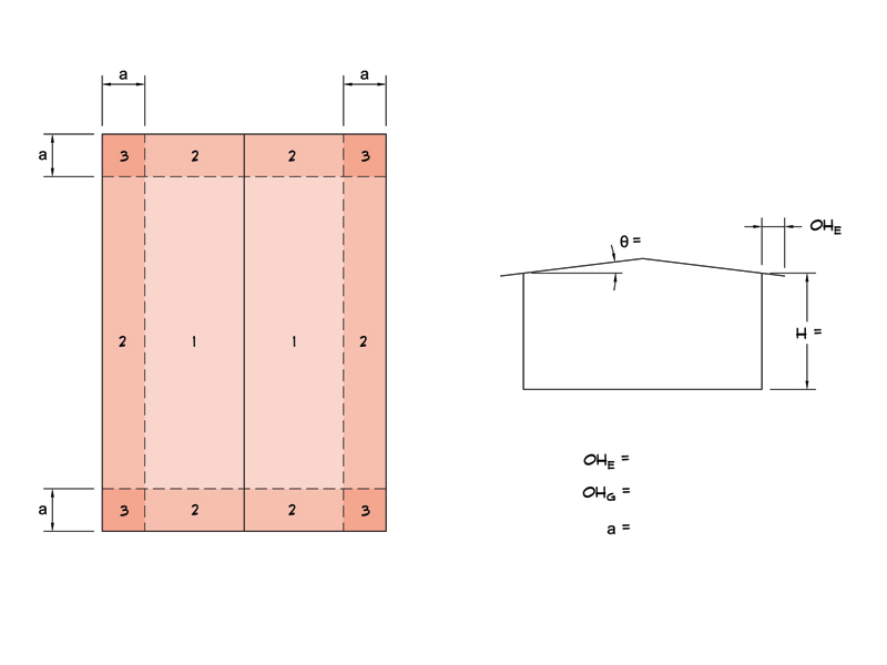
The five possible roof types would then be:

WIND_ROOF_TYPE.jpg
 
Replies continue below

Recommended for you

You might need to ask whichever newly-minted Ph.D whose dissertation drove that; the rest of us will just be guessing at his intention. But you’d probably better hurry; it’ll change again with the next code cycle and next crop of PhD’s…

(Just (half) kidding; there are a lot of sharp guys on this site and some of them will be able to help you.)
 
Another related question, and one that I can't seem to find answer for anywhere online, is what happened to the pressure zones 5, 6, 5E, and 6E in Load Case A of the envelope procedure. Yet if you turn to the commentary for chapter 28 the diagram showing the envelope procedure applied to a hip roof clearly shows zones 5 and 6 in load case A.

FIGC28.4-2.jpg


Notice also in the notes that one should use the coefficients from Table A for both Load Case A and B for a hip roof. Unfortunately, Table A is missing zones 5, 6, 5E and 6E.

I'm confused.
 
Comparing this to the 7-05 version:

FIGC6-11_2005.jpg


Why the change? Where can I find answers to the reason for the changes and an understanding on how to apply the proper coefficients to the hip roof.
 
No disrespect but I think you have a point Archie264, these questions are beyond the pay grade of most practicing engineers. I do like to ask the hard questions once in a while though. I still can't reconcile Figure C28.4-2 with the Load Case A table of Figure 28.4-1. I'm missing values for surfaces 5 and 6. Comparing tables across multiple version of ASCE 7 I've determined that the TABLE for Load Case A should include two additional columns for surfaces 5 and 6 with values of -.45 for both. These values are constant for all values of roof pitch. This then fixes the problem for hip roofs.

I am going to ask the Chair of the ASCE 7-16 Subommittee on Wind Loads to weight in at this point since I cannot seem to find a reasonable explanation for these discrepancies within the ASCE 7-10.
 
Send an e-mail to the code committee. If they are anything like the Canadian and AS/NZS groups you'll get a helpful reply quite quickly.
 
Notice the complexity when overhangs are added to the roof. These load diagrams show the Envelope Procedure for a Gable Roof:

Load Case A:

GB_A1A_800.jpg


GB_A1B_800.jpg


GB_A2A_800.jpg


GB_A2B_800.jpg


Load Case B:

GB_B1_800.jpg


GB_B2_800.jpg


If torsional load cases are required then another Load Case A and B are required for the torsional load case.
 
How accurate do you think the results will be?

See, a "perfect" wind blowing "exactly from the perpendicular side" of a perfect house with perfect landscaping (no trees, hills, slopes, bushes, or valleys) "might" at "exactly" the assumed "per Code" wind requirements would likely produce the forces that you expect from the program, right?

But those conditions don't exist in the real world of non-PhD engineering.

So, how accurate do you need to be?
( Probably, accurate enough to keep the roof on under most storms, right?)


First Set. So, I would strongly recommend NOT using the "flat-top roof with square edged walls" (Figure 3 ? in the first set) to mimic any results that might come from the other 4 typical houses. A flat roof, combined with the risers surrounding the flat roof, have NOTING in common with the sloped roofs (or curved, or cambered or or multi-sloped hip roofs) that the other roofs in Set 1 have.

Second Set: The presence of a overhang in Set 2 is significantly different for ALL of the sloped roofs from the 4 sloped roofs in Set 1. Again, that overhang causes a significant INCREASE in local whipping/turbulent loads right at the roof edge, and ADDS the overhang distance on every side to the natural lever arm of the rest of the roof in "pulling up" the roof from the walls. The overhang, increases whipping (vibration) of the overhung rafter edges, and so the whole structure is more highly stressed from winds from any direction.
 
Another engineering friend of mine with 30+ years as a structural engineer often tells me, "We're just guessing here, an educated guess, but a guess nonetheless."

I agree wind loads, snow loads and even seismic loads are bit of fuzzy math in my opinion. Nothing makes this stand out more clearly in my mind than the changes to the envelope procedure in 2002 and then back to the 1998 version in 2010 (ASCE 7). I have no explanation for the change in the first place and then no explanation why the change back. Wind loads haven't changed just our perceived understanding of them or misunderstanding.
 
I'm not sure I'm applying the positive external pressure on the bottom surface of the windward roof overhangs properly but I'm trying my best to interpret Ch. 28 as accurately as possible.

So racookpe1978 what are you suggesting with the way I'm analyzing the standard gable roof? I can understand your observations but what is the conclusion to draw from all of this?
 
I have a copy of the "Guide to Wind Load Provisions of ASCE 7-10" which I have found to be very helpful in understanding wind loads in general and the methods and techniques in using the different procedures. My only criticism of the book is that the Envelope Procedure (Ch. 28, Part 1) is mostly neglected with only one sample problem devoted to this method. This sample problem is geometrically very simple with no overhangs and a gable roof, so there is no guidance or examples of how to handle overhangs for this method.
 
Soffits experience pressures which correlate with the wall they are adjacent to.

As to your attempts to blend roof types to yield other roof types, while logical, is going to be hard to defend. Besides which the actual model will likely do things you'll find hard or impossible to predict. Whether a particular area is even negative or positive in pressure is not likely to be correct when combining models that don't have that area (the little vertical triangles on the Dutch Gable, as an example).
 
According to Sec. 28.4.3 of the Standard windward overhangs experience a positive pressure on bottom surface of the overhang (uplift) with GCp = .7

The Design pressure for this uplift would be calculated as P= qe * GCp at Load Case A since the overhangs are at the height of the eave height. For the gable overhangs I am calculating the Design Pressue using qh since the overhangs vary from eave height to ridge height.

Note that this is different from the Directional Procedure which as suggested above equates the windward overhang pressure to the wall pressure below (Sec. 27.4.4).

With the envelope procedure the max. windward wall pressure coeff. is GCpf = .56 in the interior regions (transverse case), which is different than GCp = .7.

For windward overhangs the total pressure becomes:

2EOH+W = (qh * CGpf2E) + (qe * GCp)

2OH+W = (qh * CGpf2) + (qe * GCp)

All other overhangs along the sides and leeward sides are simply the velocity pressure (qh) multiplied by the appropriate external zone coeff. GCpf, so for example 2OH denotes:

2OH = qh * GCpf2

Which is the same as zone 2 except there is no internal pressure coeff. applied.
 
Give the gable roof option a whirl, all of the other options are not programmed yet and I may never add them pending further research as to how well I can extrapolate the Envelope Procedure to these configurations.

If there are no overhangs set the overhang values to zero, I will need to add in a footnote about that later just to clarify.

Not a finished product yet, not by a long shot. The current todo list includes the following:

To Do List:

1) Calculate min. lateral load with roof forces neglected and min. pressures of 8 psf and 16 psf on roof and walls respectively. (psf)
2) Calculate max. uplift and max. horizontal reactions of trusses or rafters assuming 24" o/c and 16" o/c for design of hurricane ties (lbs).
3) Calculate base wind shear in transverse and longitudinal direction (lbs).
4) Calculate shear wall reactions (lbs) and unit shear (plf) assuming only external shear walls (4 walls).
5) Calculate roof diaphragm distributed load (plf) assuming one story building with external shear walls only.
6) Include C & C wind loads for component design.
7) Include Directional Procedure as a comparison to Envelope Procedure or setup separate calculator for this method.
8) Complete PDF report output.
 
I've just finished adding the PDF report output to the new Wind Load Calculator (Envelope Procedure ASCE 7-10). Currently it calculates the MWFRS loads, I am thinking about adding in the C&C loads as well just to complete the package. I am still undecided on how best to incorporate the half hip and dutch gable type roofs. Looking at the commentary in the back of the ASCE 7-10 it appears that one can apply this method rationally to the hip type roof which means that roof types that are somewhere in between gable and a full hip should also be safe territory as well. I've had some people tell me otherwise but really have received no good reasons why not to.
 
Compare the pressure profiles for a hip with the gable roof(Load Case A):

HP_A1A_800.jpg


GB_A1A_800.jpg
 
This is my best guess at the pressure distributions for Dutch Gable, Half Hip and Flat Roof types using the Envelope Procedure:

DG_A1A_800.jpg


HH_A1A_800.jpg


FL_A1A_800.jpg
 
Status
Not open for further replies.

Part and Inventory Search

Sponsor