Continue to Site

Eng-Tips is the largest engineering community on the Internet

Intelligent Work Forums for Engineering Professionals

  • Congratulations SSS148 on being selected by the Eng-Tips community for having the most helpful posts in the forums last week. Way to Go!

Wind Parallel to Box Truss

Status
Not open for further replies.

CrabbyT

Structural
Feb 12, 2019
165
This post mostly concerns ASCE 7-10 Chapter 29 (Wind Loads on Other Structures), but I'm curious to hear other answers if people can provide insight.

For wind perpendicular to a truss, I'm familiar with using F = q∙G∙Cf∙As where Cf is based on Figure 29.5-2.

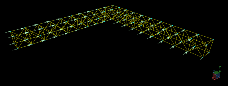
For wind acting in the longitudinal direction of a box truss (i.e. wind parallel to the truss' span), do you know of any guidance for how those forces should be calculated? Or, is there any code-justified method of using something other than Cf = 2 with point loads applied at each panel point as shown in the image below?

CrabbyTruss_nitgea.png
 
Replies continue below

Recommended for you


The picture apparently, model of a 3D open truss and frame spacing ratio ( SF / B ) seems around 1.0 . That is, each windward frame (in this case 10 ) will be loaded with basic wind load ( F = q∙G∙Cf∙As ).

In Figure 29.5-2 , force coefficient, Cf is given for various solidity ratios. Apparently , you have selected or calculated and found solidity ratio ( ∈ ) < 0.1 Cf = 2 , is for Flat-Sided Members Is that true ?

How did you calculate the wind load for vertical X bracings ? The normal practice, the vertical projected is added area normal to As.

The wind load should be applied to each element UDL rather than point loads to the nodes.
 
FYI, for anyone who stumbles on this thread, I found a good example of how to calculate the force coefficient for longitudinal wind on a pipe rack inside my copy of "Wind Loads for Petrochemical and Other Industrial Facilities" by the ASCE. They have a procedure for calculating the force coefficient, and it can be substantially higher than what I would have expected (I believe in their example, they came out with Cf = 7.5).
 

In your case, frame spacing ratio seems , around 1.0 . That is, shielding effect will diminish and each vertical bent should be loaded with code specified load and ,Cf should be around 2.0

In your statement, the example in the mentioned ref., Cf=7.5 what is the no. of frames and , frame spacing and width of the structure?

Pls look again , the wind load calculated with Cf=7.5 should be total load for the structure rather than each frame.
 
Status
Not open for further replies.

Part and Inventory Search

Sponsor