Eng-Tips is the largest engineering community on the Internet

Intelligent Work Forums for Engineering Professionals

Wood Beam Scab Repair Calculation Example 3

Status
Not open for further replies.

LowSpark

Electrical
Jan 31, 2015
23
0
0
US
Hello All,

I have a question as to why every example of a beam splice shows the load in tension as shown in this link:

Kootk from this forum gave the solution to use a beam splice in this thread but no calculation example:

The only place I have found to talk about the load perpendicular to grain is this website which used a prescriptive approach:


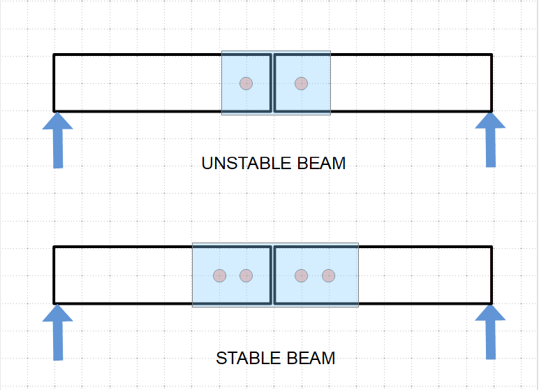
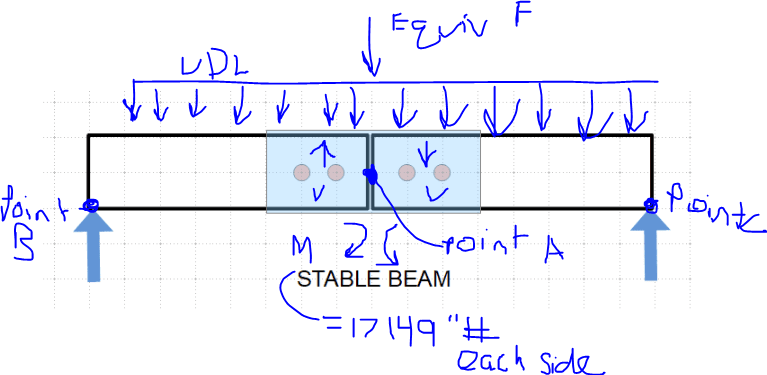
So my question is, why isn't there an example of the calculation shown in link one ( but with a uniform distributed load along the splice(such as the modified picture attached)?
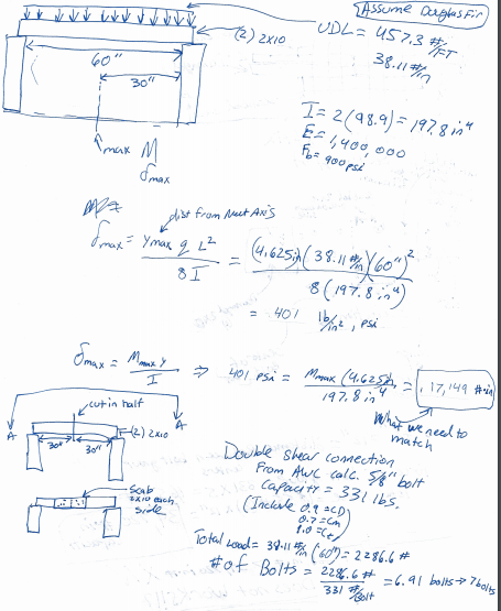
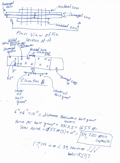
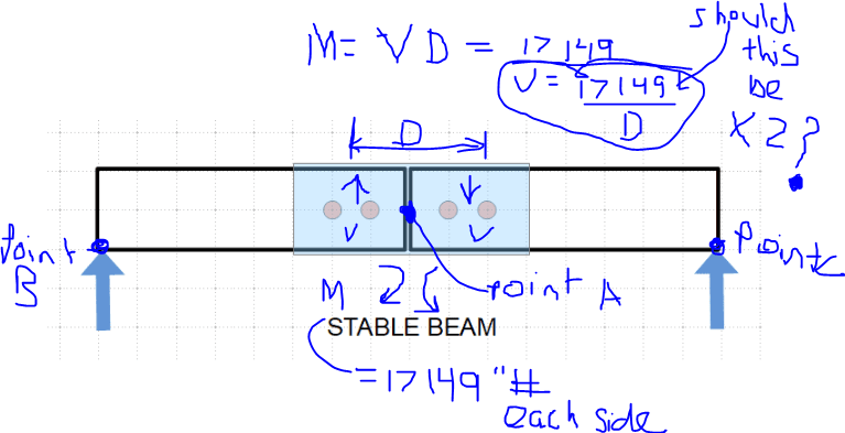

 
Replies continue below

Recommended for you

These types of connections should be avoided whenever possible. Full length sistering is preferable as the long term performance of a wood "moment connection" tends to be a bit dubious.

That said, it's not impossible. For starters, though, throw away the "summerville-home-inspector" link. Any detail that says "peppered with nails" doesn't belong in a serious engineering discussion.

The process KootK presents in that thread (and in several others since then) breaks the moment to be transferred into component parts which allows for a straightforward shear calculation with the load applied perpendicular to the grain. The calculations should be done in accordance with the NDS (year will depend on the building code adopted by the jurisdiction where the project is located). Analysis will be a matter of determining the internal moment at the splice location, split your fasteners into two groups, divide the internal moment by the distance between the fastener group centroids, and design the fastener groups for the resulting reaction. Of course, internal shear also has to be applied. That's pretty basic statics, though.
 
phameng said:
The process KootK presents in that thread (and in several others since then) breaks the moment to be transferred into component parts which allows for a straightforward shear calculation with the load applied perpendicular to the grain. The calculations should be done in accordance with the NDS (year will depend on the building code adopted by the jurisdiction where the project is located). Analysis will be a matter of determining the internal moment at the splice location, split your fasteners into two groups, divide the internal moment by the distance between the fastener group centroids, and design the fastener groups for the resulting reaction. Of course, internal shear also has to be applied. That's pretty basic statics, though.

You lay it out pretty nicely. I was thinking of looking at the problem as an equivalent areas solution. Say you have a 2x10 that is damaged in the middle of the joist and you want to repair it. You scab on the equivalent area (another 2x10) and you do it on both sides so you don't get eccentric loading. Then the length of the scab is determined by how many bolts are needed to develop the load required in the bolts and transfer it to the new 2x10 pieces.
 
It's not so straightforward as that. You have to transfer the internal stresses. So you'll have shear and flexural stresses that need to go somewhere or you'll have a beam with 4 hinges - not a good thing.

As a side note, wood screws are better for bolts in this kind of situation.

Since your tag says you're an electrical engineer and your posting history is only electrical until now, would I be right in assuming this is an issue in your house?
 
phamENG said:
Since your tag says you're an electrical engineer and your posting history is only electrical until now, would I be right in assuming this is an issue in your house?

Not an issue in my house, just an engineering curiosity. Seems like this would be a common issue that homeowners/contractors/architects would face and was interested to see why there weren't more calculated solutions to it. I believe it is important to be a well rounded engineer crossing knowledge bases between electrical, mechanical, and structural. I find wood design really interesting and enjoy looking through the NDS (weird I know).
 
Not at all. And sounds like a good philosophy.

The biggest issue is reliable performance in the connection. Wood is anisotropic, so you have variable perfomance characteristics relative to the grain direction, which itself can be somewhat variable over short distances. Since the strength varies with grain direction, you can get uneven deformations within the connection that will cause unexpected and unwanted deformations if you have loads acting in multiple directions (which is what happens if you try to resist moment with the connection). This variable stiffness is why you can't mix and match connectors in a connection. If you say a 10d nail can handle 100# and a some bolt can handle 900#, but and you need 1500# so you use a bolt and 6 nails, your connection will fail. This is because the nails are generally stiffer (tighter in their holes), so they'll take all of the load before the bolt (relatively loose in its hole) is fully engaged. The nails can only handle 600#, so they fail under the 1500# load before the bolt comes into play. When the bolt does start working, the nails are too badly deformed to carry their 600# anymore and the bolt fails because it's trying to carry it all.
 
The shear strength of two nail groups multiplied by their separation (force x distance) provides the moment strength. So, this is just a standard shear connection problem.

Nails are used because they bend (not break), and the damage is visible prior to collapse.
 
RPMG said:
The shear strength of two nail groups multiplied by their separation (force x distance) provides the moment strength. So, this is just a standard shear connection problem.

Nails are used because they bend (not break), and the damage is visible prior to collapse.

Please bear with me while I run an example by you [bigsmile] I want to make sure I understand what you mean, so I made up some numbers and tried to solve a sample situation. See attached sample problem where I try to get the needed moment capacity of the scab repair.

If I miss the mark completely please let me know if any texts that you would recommend on the subject. I tried cracking open my statics book from way back in college but it left a lot to be desired so if there is a text book out there that deals with this kind of things more I would be happy to take a look at it.

Thanks to all the replies so far.
 
 https://files.engineering.com/getfile.aspx?folder=2d6e5d20-cd03-4856-8c00-71fc89dcc6ba&file=splice_connection_2020-03-11_135741_(1).pdf
I don't download attachments, but you can upload the image

Win + Shift + S for snippet
image_cwfdu0.png
Button
Ctrl + V to paste in drop box
 
M = 17,149"# is correct on the first page.

Assuming that you calculated the capacity of each bolt group correctly (331# per bolt), the force per bolt group F is 1655# for each leaf. This would mean that F for both leaves is 3310# each side of the cut.

The error on page 2 is stating that M = 3310*12 = 39,720"# and that this exceeds the required moment of 17,149"#.

Each bolt group must be capable of resisting a moment of 17,149"#. By inspection, this connection would fail.


BA
 
BAretired said:
M = 17,149"# is correct on the first page.

Assuming that you calculated the capacity of each bolt group correctly (331# per bolt), the force per bolt group F is 1655# for each leaf. This would mean that F for both leaves is 3310# each side of the cut.

The error on page 2 is stating that M = 3310*12 = 39,720"# and that this exceeds the required moment of 17,149"#.

Each bolt group must be capable of resisting a moment of 17,149"#. By inspection, this connection would fail.

I was pretty confident about the 17,149"# because I tried to work the problem another way and I got the same answer. I basically derived the beam formula.

As for the 331# I am pretty confident that is correct, I did it by hand and I used the NDS calculator.

If each side needs to be able to resist the 17,149"# wouldn't you create an equivalent force in the midpoint (of each side) and that would give you the " # for each side? In this case 6" is the midpoint on each half, therefore, 6"*(331#*5)= 9,930"#? 9,930"# < 17,149 "# and therefore it does not work (as you said, you were able to determine this by inspection)? To get it to work I would need to make the spacing between the bolts greater. In this particular bolt pattern, the spacing would need to be ~5.5" for it to work? [(5.5+5.5+5.5+5.5)/2]*(331*5) = 18,205‬"#
 
LowSpark said:
As for the 331# I am pretty confident that is correct, I did it by hand and I used the NDS calculator.
Maybe so. I have not checked it. For our purposes, let's assume that you can develop 331#/bolt in each leaf.

LowSpark said:
If each side needs to be able to resist the 17,149"# wouldn't you create an equivalent force in the midpoint (of each side) and that would give you the " # for each side? In this case 6" is the midpoint on each half, therefore, 6"*(331#*5)= 9,930"#? 9,930"# < 17,149 "# and therefore it does not work (as you said, you were able to determine this by inspection)?

NO! 6" is not the moment arm unless the cut ends of the two 2x10 beam are connected together to resist a vertical shear of M/6 = 17,149/6 = 2858#. The cut ends of your beam are not connected at all. The resistance of your beam is closer to zero than 9,930"#. It isn't quite zero because the five bolts produce some small moment resistance.

LowSpark said:
To get it to work I would need to make the spacing between the bolts greater. In this particular bolt pattern, the spacing would need to be ~5.5" for it to work? [(5.5+5.5+5.5+5.5)/2]*(331*5) = 18,205‬"#

To get it to work, you would need to provide enough bolts on each side of the cut to resist the maximum moment as well as the shear existing at the outside connection. Using two groups each side of the cut, separated by 6" c/c, you would need a capacity of 17,149/6 + 38.11*12 = 3,315# capacity per group. The second term accounts for the fact that the shear is not zero at the centre of the outside groups.


BA
 
BAretired said:
To get it to work, you would need to provide enough bolts on each side of the cut to resist the maximum moment as well as the shear existing at the outside connection. Using two groups each side of the cut, separated by 6" c/c, you would need a capacity of 17,149/6 + 38.11*12 = 3,315# capacity per group. The second term accounts for the fact that the shear is not zero at the centre of the outside groups.


Thank you for taking the time to post this. I am going to digest this a bit later today.

Thanks again!
 
LowSpark,

In the sketch below, the scab is shown in blue and each group of bolts is represented as a single bolt shown in red. The single bolt is a pin; it can resist a force but not a moment.

The first sketch shows a mechanism with two pins near mid-span. The scab cannot transfer moment to either half of the cut beam.

The second sketch shows a simple span beam. The scab can exert a couple on each half of the cut beam (one force up, one force down) providing continuity at mid-span.

CutBeamRepair_daqefm.png


BA
 
BAretired said:
In the above calculation, it may be more economical to use longer scabs and less bolts.

Let say we use a typical spacing of 12" (with a 3" edge distance) on center for the bolts. That would yield, 39" to the last two bolts from the cut. Center of that bolt group would be at 18". Center to center of the bolt groups would be 18" + 3" (to get to the center)+3"(to get away from the center) + 18" (To get to the right side bolt group center) = 42"
17,149 "#/(18"+3") + 38.11"#*42" = 2,417#

2,417#/331# = 7.3 Bolts -> 8 bolts needed on each side? But if we use 8 bolts then the center of the bolt group wouldn't be 18". I guess it is iterative?
 
BAretired said:
LowSpark,

In the sketch below, the scab is shown in blue and each group of bolts is represented as a single bolt shown in red. The single bolt is a pin; it can resist a force but not a moment.

The first sketch shows a mechanism with two pins near mid-span. The scab cannot transfer moment to either half of the cut beam.

The second sketch shows a simple span beam. The scab can exert a couple on each half of the cut beam (one force up, one force down) providing continuity at mid-span.

Thank you for submitting this. The pin action makes sense. Looking at your stable beam I am looking at the forces/moments like this:
image_dsjrru.png

image_jzl2lz.png
 
No, that is not correct. The moment at point A is M = 17,149"#. Since the beam is cut, it can't resist any moment. The two scabs take the entire moment M.

We are assuming two pins in section A-B. Let's say they are separated by a distance 'd' (not the same as D shown on your markup). In order to transfer moment M into section A-B, the pin nearest A feels an upward force of M/d while the other pin feels a downward force of M/d. Similarly, the pins on section A-C feel equal and opposite vertical forces of M/d.

If M = 17,149"# and d = 6", M/d = 2858#. Each of the four pins feels a force of 2858#. Relative to the cut beam, the inner two are up and the outer two are down. Relative to the scabs, the opposite is true.

Note: The above calculation is for moment transfer only. It does not include the correction for shear variation. For a uniformly distributed load, shear at point A is zero. If the outer pins are 12" from point A, shear at each outer pin is 12*38.11 = 457# which affects the force on each pin.

BA
 
Status
Not open for further replies.
Back
Top