PittEng88
Structural
- Feb 14, 2015
- 90
Hi Everyone,
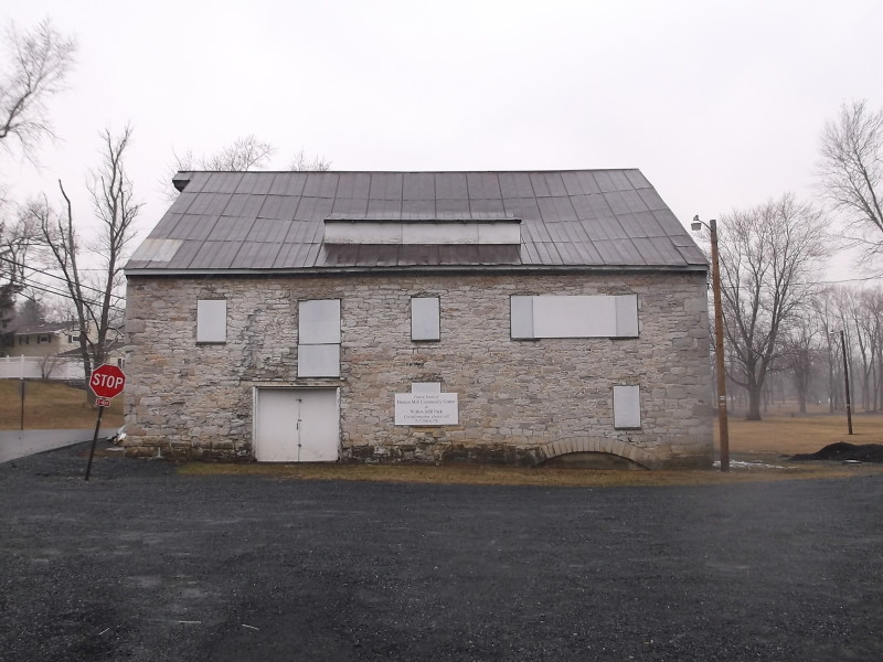
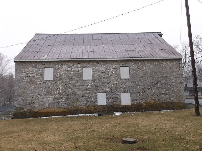
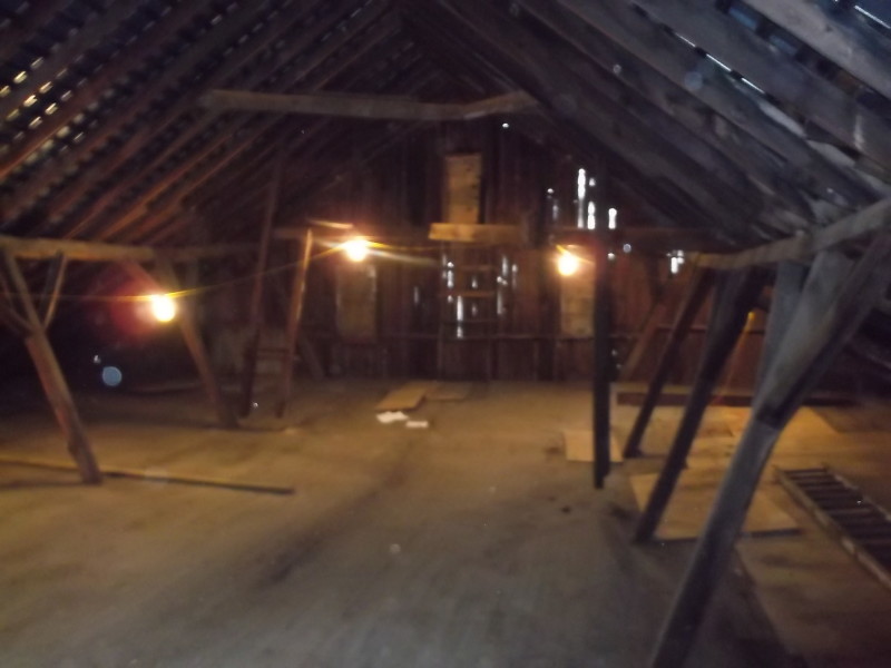
I am in the process of rehabbing a historical stone masonry building with timber framing on the inside. The walls will be repointed and the existing timber framing is to be removed and replaced. During the design process it was noted that some of the older connections for the framing would not work under the current code. So, they had to be redesigned. The roof system for this building consists of 2x8 rafters spanning approximately 25' and are supported by a 8x8 purlin at their mid-span. At the ridge, the rafters are nailed together and strapping is provided. At the eave, 2x10 Joists are used to restrain the thrust forces from the rafters. Angled 4x8 Struts every 10.5' provide support for the purlins. The vertical reaction from the strut is then transferred down into a column and to the foundation (no problem there). However, the thrust force from the strut is a different story. I ended up using double 2x10 joists (to match up with the 4x8 strut) sandwiched between two 1/4" steel plates. I welded another 1/4" plate to the back of them so that the forces can be transferred from the strut through end bearing and not through the bolts. I then called out for one 1" dia. thru-bolt to be used, to allow for rotation.
At the eave I need to provide a 1' overhang, so a welded plate at the end of the rafter will not work. Instead, I used two 1/4" steel plates bolted to the members with one 1" dia. thru-bolt in each member, again to allow for rotation.
I have provided a few sketches. The first is a section cut of the building, incase my description above was a little confusing. The second sketch is of the strut to joist connection at Detail A, and the third sketch is of the joist to rafter connection at Detail B.
I was just wondering, if you guys would be willing to give these details a quick look? Just to ensure that I did not miss/overlook anything. If you guys would like the numbers, I can provide them as well. It has been a little bit since I have designed in wood, so any comments or concerns will be greatly appreciated.
Thanks for your time,
Mike
![[idea]](/data/assets/smilies/idea.gif "[idea] [idea]")
![[r2d2]](/data/assets/smilies/r2d2.gif "[r2d2] [r2d2]")