NLOKyle
Structural
- Nov 1, 2023
- 5
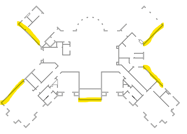
I'm having trouble determining the best way to distribute shear throughout the walls on this floor plan. If anyone has any suggestions or has designed a plan with mostly angled walls I would love to see an example. The diaphragm design force at the roof level is 30k seismic.