Continue to Site

Eng-Tips is the largest engineering community on the Internet

Intelligent Work Forums for Engineering Professionals

  • Congratulations KootK on being selected by the Eng-Tips community for having the most helpful posts in the forums last week. Way to Go!

Writing Limit Margins when Plastic Deformation Occurs

Status
Not open for further replies.

DarcyDude

Mechanical
Apr 18, 2020
13
Hello all,

Not exactly aircraft engineering, but I believe this group would have the best understanding of these topics. I work for a small company that typically designs fixed GSE. However, we are working a skid mounted project which we must verify against transport loads per MIL-STD-1791. Being that I typically work on the ground side, I'm a little less familiar with the nuance to how the Limit/Ultimate loads are handled with respect to margining. I was hoping someone may be able to clarify on a certain scenario, which I feel must be common, although I could not find addressed directly in another thread.

MIL-STD-1791 states that "Item function must be maintained up to limit load" which I interpret as meaning yielding cannot occur which prevents use of the device under the limit load case. I have generated a FEM model of our skid and at limit load there are some small areas around a set of bolt holes above the elastic limit. Running a non-linear analysis with perfectly plastic material model (A36 Steel) shows that plastic deformations are very small (0.001 - 0.002 in) certainly not enough to affect the function of the part (supporting a large hose reel). This being the case I am satisfied the design is adequate for limit loads.

However, how does one populate a margin table for this scenario? Being that I am at/above the elastic limit, it would seem margins are zero/negative (even though I think this is totally acceptable). My thought are to either:

a) write as MS = 0 with an asterisk and provide a discussion of the acceptable plastic strains as a note. OR

b) write the margin based of the the part stress away from the stress concentrator. Feels a little subjective.

I am wondering which will not raise eyebrows when reviewed by a regulator. OR if I am totally off base here.

Thanks!

 
Replies continue below

Recommended for you

If you modelled the actual holes in the FEM and connected to a fastener node with the usual wagon wheel rigid element approach, the local stresses are probably fictitious/wrong and should be ignored. But need to see a picture of the modelling details and results.
 
SW,

Correct, I am modeling with rigids at fastener hole and agree the rigid will introduce artificially high stresses. Honestly, I am always a bit fuzzy when to draw the line as to when nodes are far enough away from the rigid that results are no longer fictitious. I provided an image below, the yielding spans back a few elements off the rigid, deformations are low. There are a few spots similar to this one. Hole is 0.75 in for reference. Plot is averaged, nodal, von-mises plate stress.

I personally feel the situation is fine, but am a little uncertain how to convey that to an aviation oriented reviewing body.

HOLE_CLOSEUP_kdl7qc.png
 
Sigh. Extract the fastener load. Calc bearing stress as P/dt. Compare to Fbry. If positive margin, good to go.
 
I don't know if I would immediately agree with simply using the fastener load that way.

First off, P/dt is not always the most accurate bearing area, depending on what is actually happening to the fastener. Also, you need to determine... is the stress so high because of load transfer, or because of something else?

The stress plot you show above - are those the results from your linear model, or from your "non-linear analysis with perfectly plastic material model"?

Keep em' Flying
//Fight Corrosion!
 
Hello all,

Thanks for the replies!

SW, thank you for your guidance. I was intending to extract loads to margin the fastener and associated checks, but was maybe overthinking how far from the rigid should be ignored on the base part. I have heard to exclude the first 2X rows of elements around a fastener modeled this way, but maybe that is overly conservative.

LiftDivergence, for completeness:

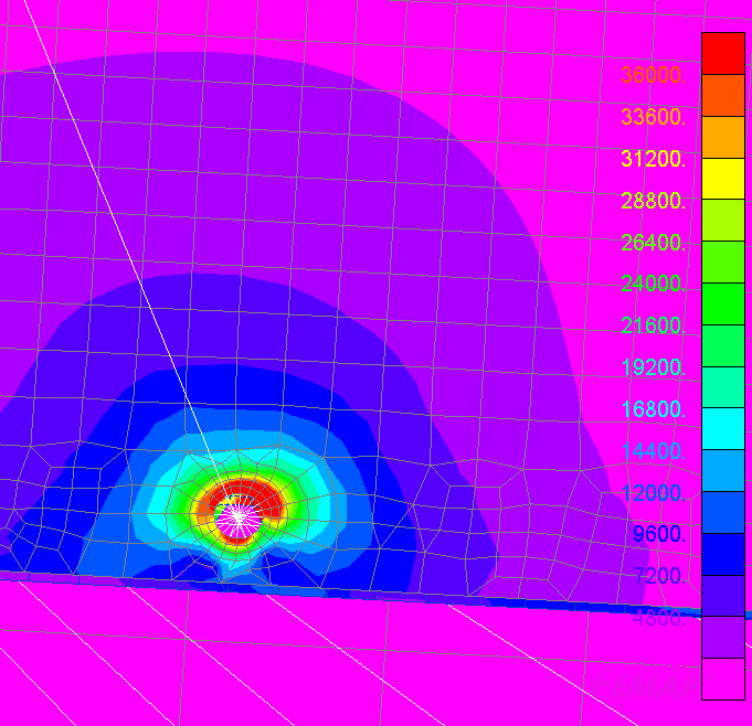
Linear:
HOLE_LINEAR_anjjzt.png


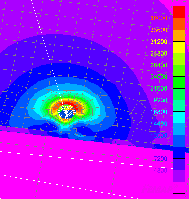
Non Linear Perfectly Plastic:
HOLE_NON_LINEAR_sywejf.png


both are scaled to yield.

Thanks!
 
it is a shame that we let pretty pictures beguile us.

FWIW, my reading of MIL-STD-1791 states that "Item function must be maintained up to limit load" does not preclude insignificant localised yielding (such as occurs at every hole in every plane). Would this localised yielding affect the function of the "item" (I hope not) ?

We should recognise that these stress peaks occur and plan to clear them with a hand calc (bearing).

another day in paradise, or is paradise one day closer ?
 
I just don't think I personally have enough information to recommend a simple bearing margin against Fbry.

We are woefully light on details...what is this fastener? What parts does it fasten together? How is it loaded? What does the surrounding fastener pattern look like?

Clearly there are some artificial stress values which result from the way the model is constructed. And standard geometric figures obviously create peak stresses which are not generally detrimental to the net section.

However, I think the first step is to understand why the results look like they do. Just saying it's a hole, you have an RBE connected to those nodes, etc, just write it off based on bearing stress calculation - that can be just as bad practice as blindly believing the stress contours.

I don't think it is unreasonable to want to see the comparison of the plots linear vs non-linear. It is interesting that there is very little difference between those plots.

For example, if it actually is an issue of bearing, then why is the peak stress on that side of the hole? It looks like some kind of lap joint with the edge of the part clearly shown. So which way is the load acting?

Keep em' Flying
//Fight Corrosion!
 
Hello All,

Thanks again for the replies/discussions! I think maybe the thread of discussion deviated a bit from my intent. I agree that these localized stresses are either a) fictitious, b) not of concern, or c) a combination of both. However, being more industrial focused in my career, I am a little uncertain how that is best communicated in a formal stress report reviewed by an aviation oriented body. Being that our company is small and not aeoro focused, I don't really have a template to go off. What is considered kosher, and the jargon surrounding that seem to vary industry to industry.

I'm thinking to margin area around bolt holes by hand based off extracted forces, and include a short discussion in the body of the report of the (acceptable) calculated plastic strains in the area just for completeness.

rb1957, no the localized yielding would certainly not affect the structure. Thank you for your advice on how to handle this scenario. You are correct I am probably guilty of giving too much credence to colors.

LiftDivergence, I don't feel very comfortable posting too many specifics on the web, but I reason that these questions are all valid. I'm hoping the detail of the report as describe above can close out these concerns for a regulator. Also note, this is not an aircraft, but a piece of industrial equipment being certified for a handful of transportation flights. As shipped, a failure would not pose a safety or large financial risk.

Sorry for posting on a common topic/situation, but it has been extremely helpful to hear how professionals in this specific industry think/talk about this issue. Unfortunately this community is the only access I have to professionals from another industry, and I appreciate your patience with my inexperience.
 
I usually use the term "modelling artifice" to describe these "nuisance" peaks.

another day in paradise, or is paradise one day closer ?
 
All I was getting at was in industry, this topic, like many things, are a spectrum. You will find many (usually inexperienced) folks who rely far to heavily on the FEM output without critical thinking. On the flip side, you have people who disposition every non-uniformity by saying it is a shortcoming of the model or an effect of the FEM approximation, write it off some other way.

In my personal opinion the best practice lies somewhere in between and I think before anyone makes a judgement call, they should fully understand the load environment. I don't fully understand your load environment, so I'm not going to tell you how you should cover off the stress peaks. I'm not asking you to post any proprietary details. Just saying, people might try to tug you one way or another but there is nothing wrong with verifying for yourself.

Definitely make sure you have an accurate sense of the bearing stress distribution on the hole surface before you write a margin against Fbry though.

Keep em' Flying
//Fight Corrosion!
 
DarcyDude. Here are some pointers -
1. Here's some background to give context for the requirement you're trying to satisfy -
The requirement in most airworthiness design standards for airframe structure and equipment is to show 'no detrimental permanent deformation' up to limit load (for reference see FAR 25.305 for one such example, rgl.faa.gov, see also the associated advisory circular).
What that means in practice depends on the type of structure. For airframe structure, "detrimental" is often interpreted as .2% permanent set (i.e. yield) but not always. A good example is single pin joints: Pin bending stresses when hand-calculated (conservative) are often in excess of yield, in this case some people use a criteria of .02* pin diameter as being "detrimental".

In short, if you can make an argument to say it's not detrimental to safe operation of the aircraft, you should be able to satisfy that requirement.

2 - In this case you're working on what could be described as role equipment, it's not airframe structure.
Even if there was some local yielding, I would highly doubt that it is detrimental to safety of flight. But that's an opinion, I don't have all the information to make that decision.

Being a cargo/interior item, is this for a crash loadcase? If so I would't worry about detrimental permanent set at limit load as it is meaningless

3- we rarely work with FEM stresses directly when immediately adjacent loaded fastener holes. Stresses around fastener details are just too complex compared to the average FEM's level of detail (hence the sighs).
Typical practice when working with FEMs is to take a fastener load from the fem, then hand calculate a bearing stress and compare it to test-derived bearing allowables (e.g. mil-hdbk-5 or MMPDS chapter 8). However note that bearing stresses are not always uniform through-thickness, especially where there is a lot of eccentricity or pin bending.

Lastly - hopefully this helps and gives some pointers for further reading, but please don't rely on this as your sole source of guidance.
 
Status
Not open for further replies.

Part and Inventory Search

Sponsor