DarcyDude
Mechanical
- Apr 18, 2020
- 13
Hello all,
Not exactly aircraft engineering, but I believe this group would have the best understanding of these topics. I work for a small company that typically designs fixed GSE. However, we are working a skid mounted project which we must verify against transport loads per MIL-STD-1791. Being that I typically work on the ground side, I'm a little less familiar with the nuance to how the Limit/Ultimate loads are handled with respect to margining. I was hoping someone may be able to clarify on a certain scenario, which I feel must be common, although I could not find addressed directly in another thread.
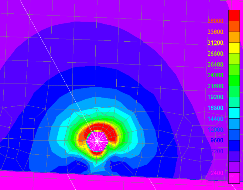
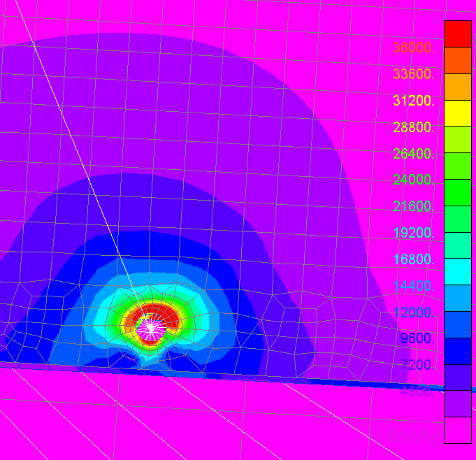
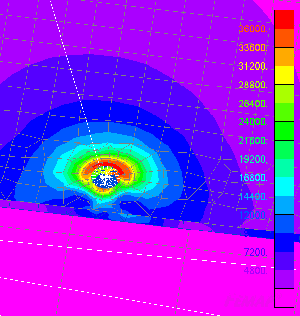
MIL-STD-1791 states that "Item function must be maintained up to limit load" which I interpret as meaning yielding cannot occur which prevents use of the device under the limit load case. I have generated a FEM model of our skid and at limit load there are some small areas around a set of bolt holes above the elastic limit. Running a non-linear analysis with perfectly plastic material model (A36 Steel) shows that plastic deformations are very small (0.001 - 0.002 in) certainly not enough to affect the function of the part (supporting a large hose reel). This being the case I am satisfied the design is adequate for limit loads.
However, how does one populate a margin table for this scenario? Being that I am at/above the elastic limit, it would seem margins are zero/negative (even though I think this is totally acceptable). My thought are to either:
a) write as MS = 0 with an asterisk and provide a discussion of the acceptable plastic strains as a note. OR
b) write the margin based of the the part stress away from the stress concentrator. Feels a little subjective.
I am wondering which will not raise eyebrows when reviewed by a regulator. OR if I am totally off base here.
Thanks!


