Eng-Tips is the largest engineering community on the Internet

Intelligent Work Forums for Engineering Professionals

WTF is this roof framing?

Status
Not open for further replies.

SinStrucEng

Structural
Nov 11, 2022
59
0
6
CA
The question is simple: WTF is this roof framing? I have never encountered this before and it's super odd to me. Looking for any information...

Specifics:

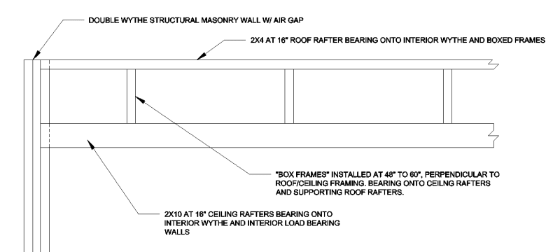
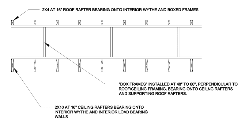
3-storey above grade building (no basement) with flat roof is in Ontario, built in late 50s/early 60s according to the new owner. Structural masonry walls (double wythe) all the way up. CMU foundation walls. There are central load bearing walls and the floor/roof framing runs in the short direction of the building. Floor framing is 2x10 at 16" with one end supported by the inner wythe of the exterior walls and lapped over the central walls.

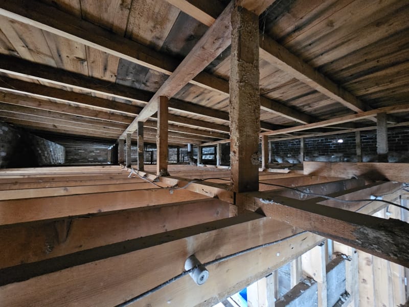
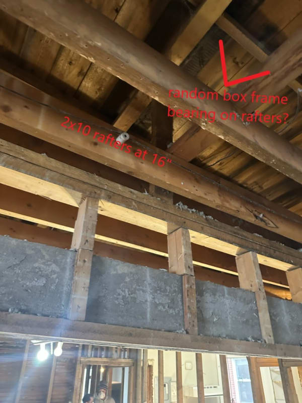
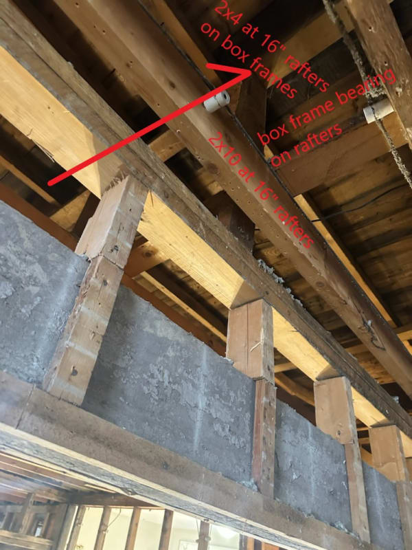
But the roof framing... the ceiling of the top floor is 2x10 at 16", as with the floor, but then there's these "box trusses" (which aren't actually trusses) that run in the long direction and bear onto the rafters. These box frames (which are spaced like 6 to 8 feet apart) create a roughly 24" plenum space which was filled with insulation prior to abatement. On the box trusses, additional 2x4 rafters at 16" are installed in the short direction, parallel and generally in line with the 2x10 rafters framing the ceiling.

Why? What is this?

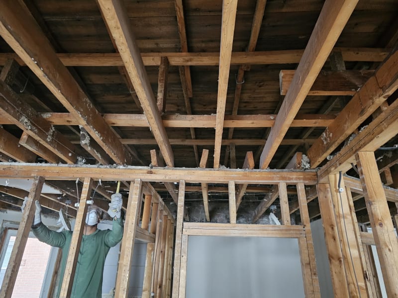
Client simply wishes to tear out a wall that is generally non-structural IMO so that's not a problem, but... I'm just confused by this method and would like some insight. This entire interior was lathe and plaster before the client demoed it all to expose the wonky framing. There are other oddities inside but this is the weirdest for me... Going back tomorrow AM so I can take more images if needed.

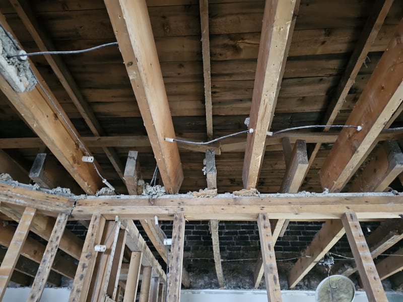
What is most odd to me is that the 2x4 upper rafters were installed at the same spacing and almost identical spans as the lower 2x10 rafters. They take the roof load and somehow this was OK? I wonder if this was OKed at the time because they were permitting these 2x4s to deflect whereas the interior 2x10 was stiff for finish requirements. Yet that still seems like a stretch to me.
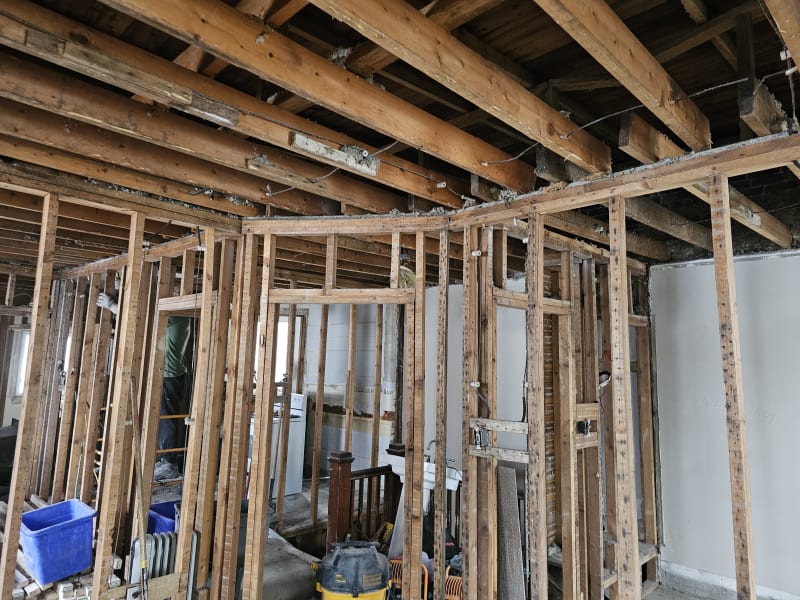
1000027408_bsz0tk.jpg

1000027409_eabx1p.jpg
 
Replies continue below

Recommended for you

Sketch a section and we might be able to understand what's going on. Also, what's a "box frame"?

It kind of looks like you have a short bearing wall above the 2x10's which would act a bearing line for your 2x4 roof framing. If that's the case yes I've seen this before. The ceiling framing is also carrying roof load. It saves material for longer span ceiling framing. Built before gang-nail trusses.
 
Hi Harbringer. Sketches are pasted below. They aren't pretty, but they're quick...

I have no clue what these repeated frames are, so "box frame" is my rinky dinky forum terminology while I get educated. I tried to find them online but found nothing. I guess you can call them a pony bearing wall or something similar. Perhaps that's all they are.

I agree that the ceiling rafters (the 2x10) are carrying the roof load, 100%. I'm more curious about why this framing was done this way and what considerations I should keep in mind when dealing with it. Thanks for your input.


Elevation_View_wgs3p6.png


Cross_Section_View_unrgpp.png
 
The box frames look to be transferring the roof load to the CJ's as the rafters are undersized and providing the slope. See this a bunch in my area in older masonry buildings.
 
Could it be that there was plans for another story? 2x10@16 seem more like a floor joist. And then they built the roof with box frames to create the slope etc.?
 
SinStrucEng said:
WTF is this roof framing
I've seen weirder in-situ framing, and have decided that for my own mental health, I am no longer going to try and understand the decisions or thought processes that have gone into the odd-ball wood framing that I come across. I am sure it made sense to someone, but it's often not me.

Whatever might have been the original intent, this system creates a cavity for roof insulation and other services (electrical, mechanical). Quite nice, since it likely prevented the ceiling joists from getting drilled to swiss cheese by a century of careless service upgrades. And yes, I agree with SWComposites that the knob and tube shown was NOT installed in the 50s or 60s - this building is older. 50s wiring in my neck of the woods (Alberta) was generally quite hefty copper wire with a textile insulator.

The 2x4s only need to span 4-5 ft between the box frames and likely have catenary abilities due to the multi-span nature of each joist. Consider that and the fact that the wood is likely old-growth Douglas Fir with hair-width growth rings (can probably consider it to be SS grade in current material properties tables), and I'd wager that deflection works out. The box frames are simply creating vertical space, and the ceiling joists are doing the heavy lifting. Looks like it's all rough sawn as well, which gives you a good bit of extra meat in the components.
 
Hi All,

Thanks for replying. I agree with all of you on the load paths, and it's interesting that the building is older than the owner believes. I don't pretend to be competent in electrical/mechanical matters so I stay in my lane, as they say :) In any case, I went back to the site today and got better pictures. The box frames were broken in quite a few spots, and I have the contractor fixing them by replacing broken elements and then laminating 1/2" plywood (much like truss repair methodology) on each face. The ceiling rafters are rotating quite a bit so I have them installing blocking where rafters are lapped to prevent further rotation before closing it all back up.

Quite interesting to me. I agree with @Craig_H and will stop to try and figure out why the ancients have done the framing this way. Clearly it didn't work out because the top chords of the box frames have broken in many locations and the roof rafters are (IMO) spanning way too far. We have rough winters here and our snow load is 2.44 kPa, and then we also have to consider access loads and dead loads.

The "Box Frames".
20240201_101107_noguy5.jpg


Rotating ceiling rafters.
20240201_102645_ycq0en.jpg


Top chord at the box frame is broken...
20240201_102551_cki9yt.jpg


General framing... Note no headers above openings in load bearing walls.
20240201_102845_srw2wb.jpg
 
just seeing old post and tube wiring again gives me cold shivers remembering ripping all of that stuff out of two early 1900's Seattle houses I owned.
 
I agree with J, They were thinking of going taller and put in the 'std floor'.
But then for whatever reasons (money) the quit at 3 and decided to frame out a roof that could be stripped off later.
Why the funny box things is anyone's guess.
It is likely that the last reno was in 50s/60s, but construction goes back 100 years.
Try not to alter any original work as you will be unable to match lumber dimensions.

= = = = = = = = = = = = = = = = = = = =
P.E. Metallurgy, consulting work welcomed
 
I wouldn't call those box frames, I'd call them knee walls. This is pretty typical in my area for older buildings, especially in the older down-towns with rows of adjoining buildings with monoslope roofs going back to an alley.
 
does "cowboy" describe it ?

"Hoffen wir mal, dass alles gut geht !"
General Paulus, Nov 1942, outside Stalingrad after the launch of Operation Uranus.
 
This is reasonably common in Ontario for certain types of older structures. In my opinion, a beautiful example of how things used to be constructed. Something must have been done reasonably well for it to last 100 years. Reminds me of the rough sawn 2x8 floor joists in my house that are 30 feet long as single pieces (two span), you just don't find wood like that anymore. In my opinion this type of framing has nothing to do with future storeys being added.

When I have seen framing arrangements such as this, the ceiling joists are horizontal and the roof joists are sloped for drainage. I have not figured out why the size of the attic space is as tall as it is, but have seen it many times in Ontario and Quebec. Deteriorated wood needs to be identified and fixed. It's a good idea to run some calcs to justify the existing framing, but remember that wood of that age is stronger than modern day tabulated values. Samples can be taken for species identification if necessary to refine design values. I am reasonably confident the original construction intent was for the pony walls to provide support for the roof rafters.
 
Thanks Canuck. I won't be taking samples or anything, however, since I am having them leave the framing as-is. It's grandfathered as it is and I didn't see any signs of rot, dry or wet. No framing changes to the rafters (ceiling or roof). Only modifications being done are to the pony walls ("box frames", so others can follow the thread) and only where they are disjointed or broken. In those instances it'll be a plywood lamination to both faces with installation of additional web stiffeners (or studs? whatever).

Personally I agree in that I don't think there was ever an abandoned additional floor; this is clearly for the support of the 2x4 roof rafters.
 
Status
Not open for further replies.
Back
Top