Eng-Tips is the largest engineering community on the Internet

Intelligent Work Forums for Engineering Professionals

ZN worm profiles question 2

Status
Not open for further replies.
Apr 19, 2021
24
0
0
GB
Hello,

As described in my other thread ZK worm parameters, I am working with an existing software application that generates dressing programs for different types of threads and worms and I am currently working on fixing a reported issue with ZN type worms in the application.

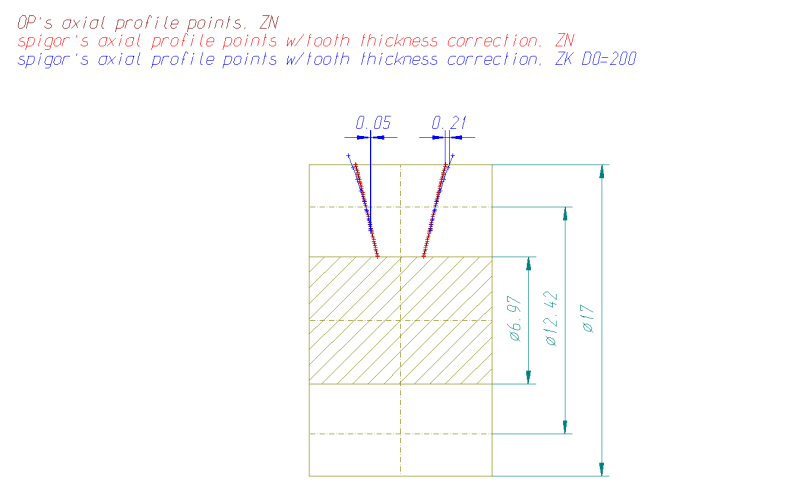
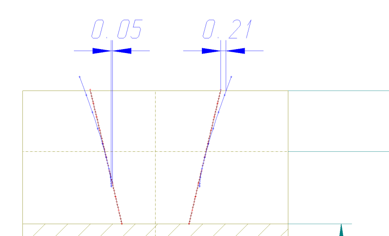
So far, I have been able to produce a NC program for a Siemens 840Dsl CNC machine from calculated profiles, but whenever we grind a part on the machine, the profile has always been wrong, i.e., the flanks are more curved than we think they should be.

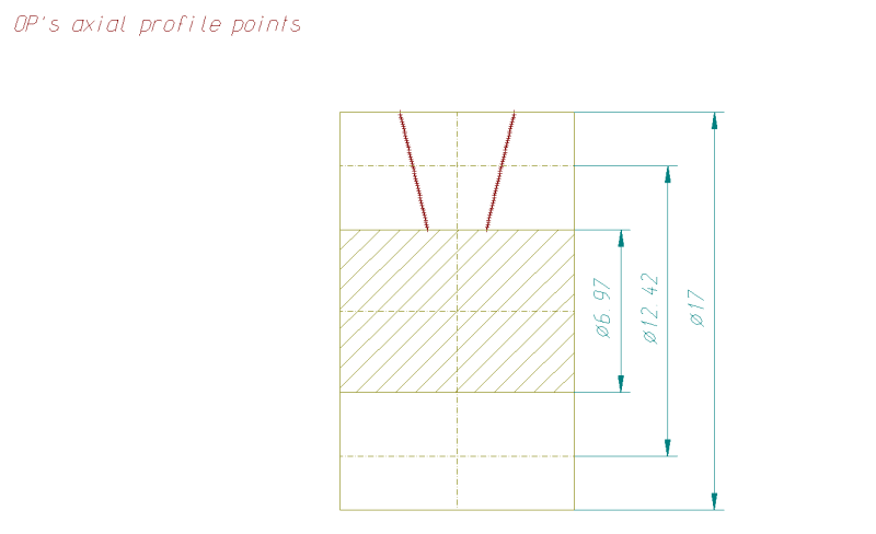
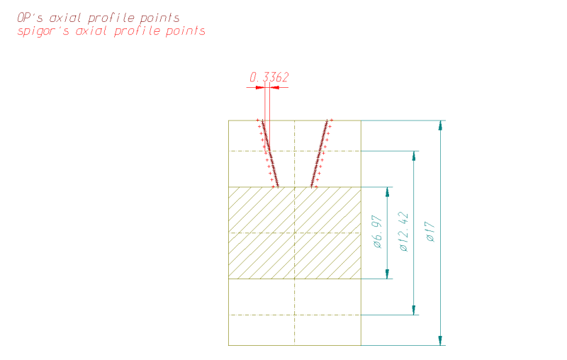
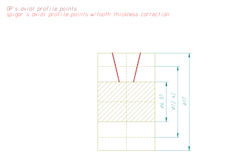
I have the data for 2 ZN worm parts provided by our customer who reported the issue and I have posted some of the details below for the first one:

[ul]
[li]Worm Type: ZN[/li]
[li]Number of teeth: 2[/li]
[li]Single lead[/li]
[li]Right handed[/li]
[li]Pitch circle diameter: 12.42 mm[/li]
[li]Tip diameter: 17 mm[/li]
[li]Root diameter: 6.97 mm[/li]
[li]Helix angle: 20.14 degrees[/li]
[li]Flank angle: 14.5 degrees (for both LH and RH)[/li]
[li]Lead: 14.311 mm[/li]
[li]Normal plane angle: 20.14 degrees[/li]
[li]Tip fillet radius: 0.5 mm[/li]
[li]Root fillet radius: 0.5 mm[/li]
[li]Measuring wire diameter: 4.7455 mm[/li]
[li]Size over the wires: 19.77 mm[/li]
[/ul]

We also have a setting that controls the number of points that are generated on the flanks, and this value is set to 50 in this case.

One thing I will point out is that we have a "Normal plane angle" parameter which we always set to the helix angle.

I also have copies of log files created by the software for the worm profiles on the normal and axial planes and I will attach them later as I cannot seem to do this from the office.

Edited to add normal (ZN_SingleLead_NormalPoints.Dat) file, which has the format of (I'll post the axial one in the next post):

[ol 1]
[li]No. - this is the point number[/li]
[li]Width(mm) - this is the profile width (X coordinate) for each point[/li]
[li]Radius(mm) - this is the profile radius (Y/Z coordinate) for each point[/li]
[li]Normal(deg) - this the angle from the X axis to the outward normal vector from this point[/li]
[li]Attribute - this is a point label identifying where the point is on the profile[/li]
[/ol]

I was wondering if someone could kindly help me generate the worm profiles (ideally both the normal and axial plane ones) and compare them against the attached result files please?

If there is any other information you need, please let me know.

Best regards,

Richard

 
Replies continue below

Recommended for you

Richard

if there is an issue with the design it is not a manufacture issue. grinding the worm should not be this difficult.
the control inputs should be straight forward. and is usually done in the normal data then calculated to obtain the axial or transverse data.
software like geartrax or MIT is required and both the worm and worm gear data is required. then it can be analyzed for interference
at the tooth contact and proper tooth geometry & clearance. do you have the mating worm gear data?
did you receive the sample part from the customer. and do you have a gear checker to analyze it.
Please do not be offended but we are running circles. the MIT worm gear module id not very expensive, and gear trax is also very inexpensive.
if yo can give us more data I will buy the MIT software module to run the numbers.
 
OP said:
I was wondering if someone could kindly help me generate the worm profiles (ideally both the normal and axial plane ones) and compare them against the attached result files please?

To generate e.g. by means of a CAD simulation of the machining process, or to calculate with mathematics?

I could not find the file ZN_SingleLead_NormalPoints.Dat

Are you able to use CAD to compare profiles? You didn't make any comment on the ZN, ZI and ZK profiles I calculated in the previous thread with some issues being repeated in this thread. There are online dxf viewers like or available.

First I took your ZN_SingleLead_AxialPoints.Dat file and imported it into CAD to see the points on a sketch of the worm.
1_wqc4s6.png


The tool is a flat reference profile, tilted 20.14° with 14.5° profile angle. Assuming both flanks are generated at once (duplex mode - it's an important assumption, having influence on the end geometry of the worm) because no other information is given, I calculate the tip width of the tool at ø6.97 (root diameter) in its normal plane from the wire measurement to be 2.8271 mm. BTW I calculate this assuming a ZI worm - for a good reason that should become obvious at the end, so there will be a little difference between the tooth thickness on the reference diameter between ZN and ZI, which can be seen in the dxf file I have attached in the previous thread.

The interaction with the tool can take place only on its edges (by definition of a ZN worm). I can now take any point on the tool's edge, calculate the angle φ it is displaced from the axial plane, rotate it by -φ around the X axis so it travels into the axial plane (Z=0), and translate it axially by φ/360*axial pitch. E.g. I take the point on the normal profile of the tool:

x; y; z
1.41355; 3.485; 0

I tilt it by the lead angle 20.14° and get:

x; y; z
1.327103; 3.485; -0.48675

Now I rotate it and move to the axial plane as described and get:

x; y; z
1.643177; 3.518828; 0

Now I do the same with let's say 10 more points:

x; y; z
1.643177; 3.518828; 0
1.750705; 4.021763; 0
1.861398; 4.52482; 0
1.974306; 5.027963; 0
2.088826; 5.531168; 0
2.204554; 6.03442; 0
2.321212; 6.537708; 0
2.4386; 7.041023; 0
2.556572; 7.544362; 0
2.675018; 8.047718; 0
2.793855; 8.55109; 0

I import that into CAD:
1_yyhqoo.png


Looks like the wire measurement is wrong again, or we are not using the same definition of wire measurement. Mine is to take 3 wires, put the worm onto two on a measuring table, insert the third wire on the top and measure with a height gauge. I take a correction and get:

x; y; z
1.273618; 3.505342; 0
1.389958; 4.008747; 0
1.507509; 4.51217; 0
1.625905; 5.015606; 0
1.744916; 5.51905; 0
1.864388; 6.022501; 0
1.984213; 6.525958; 0
2.104316; 7.029418; 0
2.224642; 7.532882; 0
2.345147; 8.036348; 0
2.465802; 8.539817; 0

1_i1zw70.png

1_jgfunf.png


The OP's points match my points w/correction over the entire profile.

I suspect you use the points in the normal plane to shape your grinding wheel. As stated in the previous thread, that would not be correct because the wheel will grind outside the normal plane. With a 200 mm wheel it would look like this:
1_bfishw.png

1_dgqpad.png


So, to grind a ZN worm with a disc shaped tool, you need corrections on the tool which will compensate for the differences between the ZN and the ZK geometry.

Last but not least - the tool tilt angle does not have to be equal to the lead angle on reference diameter (here 20.14°). Using a different angle and corresponding corrections may sometimes be beneficial end is used e.g. in grinding of helical gears.

Hope it helps.
 
mfgenggear: we did receive a ZN part from the customer along with its associated drawing, but it's a wider part. The data I've been using is for the part they were trying to grind when they first reported the issue to us (and this is before I joined the company).

Yes, we do have a gear checking machine in house, one may by Wenzel, and we use that for measuring the parts ground: this is showing the customer-supplied ZN part with straight flanks and the ones we grind in house with curved flanks.

I'm afraid we're only ever given the data for the worm gear itself not the mating wheel.

And thank you for the YouTube link, I'll have a look at that as well.

spigor: thank you for running those through and I'm sorry about the missing file - I thought I'd included, but obviously not, so I'll add it in later.

I've been trying to fix this ZN issue for over 18 months now: unfortunately, no one else in the company really understands the details of how this software works beyond some high level stuff, so I've been trying to learn it all myself (and failing), since everything I try leads to the ground worm having curved flanks.
 
Hi spigor - I forgot to answer your question about using CAD simulation or generating the profile mathematically: what we're doing is trying to generate the profile mathematically.

Also, on further reading, it seems that the ZN worm should have slightly convex flanks on the axial profile, but we're seeing much quite curved flanks.

The drawing we were given showed them using the 3 wire method for measurement as well.
 
Are you not trying to grind a ZN worm with almost straight flanks (in its axial plane), but instead you get the flanks curved by around 0.21 mm per side on the outer diameter Ø17?
 
We're trying to grind a ZN worm which should have straight flanks in the normal plane but there are still some curves/deviations on the profile.

I can upload a screenshot of the measurement results to the thread if that will help (unfortunately, the printer connected to our measuring machine is currently faulty so we can't get the automatic report print outs from measurements).
 
Richard

focus on the grinder:
Please verify if the manufacture of this machine is still in business, try to obtain operators manual.
if not. talk to dealers and try to obtain a used operators manual. this will walk you through the steps for programing
and will make life easier for you.

if permissible, take a screen shot of the display panel for our review. again what are the inputs on the machine.

foucus on the master.
with the data provide
take a measurement over two wires and then take a measurement with three wires. and record. verify if it correlates to the data.
(does the cnc gear checker have a worm program?)
if the part has centers it will be easy to inspect in the cnc gear checker, if not tool it
if the data is correct to the part, it will have a correct profile and correct lead.
if not then there is error in the data.


mfgenggear: I work for the manufacturer of the grinding machine, and it's based on the Siemens 840Dsl CNC as we're a Siemens OEM.

The software runs on a Windows PC - Siemens use one of these to operate the machine's control panel, the only other part is a 2nd application that fits in with the Siemens HMI and allows the operator to enter the part data (it uses a database to store all the details), and this then passes the data to the application I'm working on to actually perform all the calculations to generate the NC dressing program.

The inputs for both applications are what I've already listed -

With some further testing today, we've managed to get the profile almost straight with some minor deviations on the ground profile, which is what I'm looking into as well, I was hoping to get some confirmation on what I'm doing.

Edit to add: ZN_SingleLead_NormalPoints.Dat file I missed off previously.
 
I would like to ask somebody else on this forum, presumably with better English skills than mine, to explain what I've been trying to explain many times, apparently with no success:

It is very probable that the OP is grinding a ZN worm with a disc shaped grinding wheel with no corrections on the profile, hence the OP is grinding a ZK worm instead. I assume that since the axial profile of the worm, as delivered by the OP, is correct, and since the axial profile of the worm must be derived from its normal profile, it implies that the normal profile is also correct. This normal profile is probably used to shape the grinding wheel, and as a result a ZK worm is being ground. I have already shown two times, that the ZK worm has flanks that are more curved than the ZN worm.

Thank you in advance.
 
Just to add some clarification, our application works with ZI, ZA, ZN and ZK worms - their profiles are transformed to the axial plane before we create the wheel profile, dresser disc profile and dressing program, so the ZN worm's wheel profile is not being calculated on the normal profile. (The ZK worms is a separate project if you like that I've been asked to look into.)

There are options for adding relief at the tip and root as well as profile correction (we offer lean and bend correction options). I could put together a flowchart to describe how the application works at a high level if that would help explain it better?

We have been able to get back to an earlier version of the application that shows almost straight flanks on the ZN worm profile when it is ground on the machine, but it does still have a few "bumps" in it, which I am working on correcting.
 
Quote from
Response provided by Hermann J. Stadtfeld, vice president - bevel gear
technology - R&D for Gleason Corporation.

Worm Gear Generation and their Manufacturing Tools
The question will be answered considering the different possibilities in profile form,
kind of mesh, and type of tools. Figure 1 contains the general nomenclature used to
define the geometry parameters.
Worm gear drives can be separated in three categories:
Case A. Crossed helical worm gear drives
Case B. Cylindrical worm gear drives
Case C. Double-enveloping worm gear drives
Cylindrical worm gear drives “B” are the most common form. Their tooth profiles of the worms depend on the manufacturing method. The different profile forms
according to DIN 3975 are:
ZI: Tooth profile in face section is an involute; manufactured, for example, by hobbing,
like a cylindrical pinion. The hob for the worm gear manufacturing is a “duplicate” of the worm (however serrated and considering clearance and backlash).
ZA: Profile is a trapezoid in an axial section; manufactured, for example, by turning.
ZN: Profile is a trapezoid in a normal section; manufactured, for example, by turning
with cutting blade tilted to lead angle of worm.

ZK: Profile with crowning. Tool is disk cutter with trapezoidal profile, which is tilted
to lead angle of worm. Profile crown generated depending on disk cutter diameter.

ZH: Disk cutter with convex cutting edges, causing hollow flank profiles in axial
section on worm teeth.
Disk cutter axis is parallel to worm axis (not
tilted like ZK).
A. Crossed helical worm
gear drive. This is a special case of crossed helical
gears, where the worm is a
helical gear with one to six
teeth, and the worm gear
has a high number of teeth
(e.g., above 30). The pitch
elements of a crossed helical worm and worm gear
are cylinders (Fig. 2). Both
members—worm and worm
gear—are manufactured
like helical gears, with standard hobs, for example. The
profile of both members is
involute. The hobbing tool
in Case A is not identical to
A gear handbook in my possession states: The ZI worm is identical to
an involute helical gear whose tooth number is the number of worm
threads. Equations of tooth surfaces of an involute helical gear are the
same as for an involute worm. Knowing that a ZI hob cutter is identical
to a ZI worm, I conclude that the mesh of the ZI worm and involute
helical gear is identical to a cross involute helical gear mesh; and even
identical to the hobbing process of an involute helical gear with a ZI
hob cutter.
I would like to know whether I am correct and what is their difference.
QUESTION #2
Figure 1 Worm gear drive nomenclature, single-throat
example (graphics courtesy of G

definition of a trapazoid
trap•e•zoid (ˈtræp əˌzɔɪd)

n.
1.
a. a quadrilateral plane figure having two parallel and two nonparallel sides.
b. Brit. trapezium (def. 1b).
2. the mammalian wrist bone that articulates with the metacarpal of the second digit or forefinger.
adj.
3. Also, trap`e•zoi′dal. of, pertaining to, or having the form of a trapezoid.
[1695–1705; < New Latin trapezoīdēs < Late Greek trapezoeidḗs trapeziumlike. See trapezium, -oid]
Random House Kernerman Webster's College Dictionary, © 2010 K Dictionaries Ltd. Copyright 2005, 1997, 1991 by Random House, Inc. All rights reserved.
click for a larger image
trapezoidtrap·e·zoid (trăp′ĭ-zoid′)
A four-sided figure having two parallel sides.
The American Heritage® Student Science Dictionary, Second Edition. Copyright © 2014 by Houghton Mifflin Harcourt Publish
click for a larger imagetrapezoidtrap·e·zoid (trăp′ĭ-zoid′)
A four-sided figure having two parallel sides.

 
OP said:
...what we're doing is trying to generate the profile mathematically.

Right on. I will now expand on the calculations to show their mathematical side a bit more.

I have the reference diameter 12.42 and axial pitch 14.311, so I need to calculate the lead angle on reference diameter exactly:
γ=atan(14.311/Π/12.42)=20.141722°

We have got a point on the tool's edge:
x; y; z
1.41355; 3.485; 0

That's because the tip width is 2.8271 mm, we are looking at first point on the tip, so it's x=2.8271/2=1.41355. The tool will reach down to the root diameter of 6.97, so it's y=6.97/2=3.485

I tilt it by the lead angle γ and get:

r=x=1.41355
x'=r*cos(γ)=1.41355*cos(20.141722°)=1.327103
y'=y=3.485 (we are rotating in the xz plane, y stays the same).
z'=-r*sin(20.141722°)=-0.48675

x; y; z
1.327103; 3.485; -0.48675

I calculate the angle φ this point is displaced from the axial plane:

φ=atan(z/y)=atan(-0.48675/3.485)=-7.95101°

Now rotate it and move to the axial plane:

r=SQRT(y^2+z^2)=SQRT(3.485^2+(-0.48675)^2))=3.518828
x=1.327103-14.311*(-7.95101)/360=1.643177
y=r=3.518828
z=0

x; y; z
1.643177; 3.518828; 0

I have calculated 11 points on the tool's edge like this, every 10% of worm's profile height. Since the da=17 and df=6.97, the next point is located on height calculated as follows:

17-6.97=10.03
10%*10.03/2=0.5015
6.97+0.5015=7.4715
y=7.4715/2=3.73575

The profile angle is 14.5°, so the x coordinate on the profile at height 0.5015 is:
x=1.41355+0.5015*tan(14.5°)=1.543247

x; y
1.543247; 3.9865

If I repeat the whole calculation procedure with above profile point I get:

x; y; z
1.750705; 4.021763; 0

This is a second point on the ZN profile as shown in the message dated 28 May 21 12:28 above.

Now you have a complete explanation with example points calculated on how to calculate axial profile of a ZN worm. The results of this calculation match those delivered by your software.

Is there anything else that is not clear in this thread?
 
Richard

how is the project proceeding? making head way.

looking at your competitors videos, they dress with a diamond disk in x axis, then tilt the wheel to the lead angle. it appears the the wheel is trapezoid,
but straight sided, however they don't specify the worm data, or what type of worm. could be ZA. the grinding appears in the normal plain. however what I don't know if it is fed in on x axis. I imagine the wheel has a C axis for tilting.
in the gear shop I worked at for the last 30 years, when cutting a helical or spur gear, the hob lead angle was compensated by swiveling. in other words when hobbing a spur gear
the hob would be swiveled to machine a straight lead. compensating for the hob lead angle.+/- the helical gear helix. a helical which would be similar to a worm would be swiveled to obtain the correct helix angle.
or the correct lead angle. and allowing for errors, could be slightly compensated to obtain a straight lead with the cnc gear checker, old days it was a fellows lead checker.
the correct involute would be produced by the hob profile, Reishauer gear grinder grinds the gear with a worm wheel as well. some smarter people than me figured out the dressing
of wheel to obtain the correct profile and lead. on our old hobbers I believe (I am forgetting some facts) the hob was fed in on x axis.
so from observing the videos, wheel was dressed while straight, then tilted and fed into the part with the correct rpm, to obtain the correct lead. so it appears to be grinding in the normal plane.
here is a screen shot of the rack I drew
 
mfgenggear: The grinding wheel tilt angle was assumed 20.14° which is the lead angle at reference diameter Ø12.42. But at the external diameter that angle becomes atan(14.311/Π/17)=15°, while the wheel is still set at 20.14°. The wheel will therefore grind outside the normal plane except for the reference diameter of the worm.

 
Spigor

and I believe you, I never had to dig this deep before on worm geometry. but every machine I worked on as a kid and as an apprentice.
we would swivel to the lead or helix angle. and the helical gears lead would be correct. now I trying wrap my head why on worms. why it would be different.
some of my mentors who were way better at math, than I am were guys from Invo Spline, ACR, and western gear. and they don't exist any more.
I stopped hand calculation manually years back because of time constraints and got lazy. I use to write my own equipment specific excel spread sheets
for equipment specific settings and data for the operators.
one note I do remember is the helix or lead must be specifically stated as were it was calculated from, on the designers print. so there is no issues with the calculations.
Please advise who the authors were that you were able to derive the above formulas, so that I can double check your formulas.
I would like to write my own spread sheet for future general purposes, but this issue may never repeat again, but who knows.

 
Status
Not open for further replies.
Back
Top