Continue to Site

Eng-Tips is the largest engineering community on the Internet

Intelligent Work Forums for Engineering Professionals

  • Congratulations KootK on being selected by the Eng-Tips community for having the most helpful posts in the forums last week. Way to Go!

Question on basic dim/ Datum Scheme

Status
Not open for further replies.

MechEng1744

Mechanical
Jul 21, 2020
7
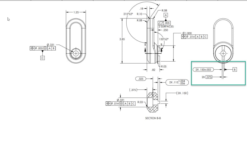
Another engineer made drawings at our company, and our inspection group is questioning this practice. Do all basic DIM HAVE to come from datums? Is this a valid scheme? If you can point me somewhere in y14.5 that would be helpful. I have a feeling this is legal, but I cant find out how... Thanks!
2020-07-21_9-46-42_m5gq6o.jpg
 
Replies continue below

Recommended for you

I believe this means datum B is the center of the slot, is this correct?
 
Will do thank you. The scheme used in the green box above is valid, correct? It is stating datum B is in the center of the slot, left side is a theoretical 0.75 away, and slot width is .150, correct?
 
MechEng1744 said:
I believe this means datum B is the center of the slot, is this correct?

Yes, it is correct.

Since they are 2 features of size, you may want to tie them together with a <CF> modifier, or Position callout.
 
Do all basic DIM HAVE to come from datums?

No. One example would be basic dims used to space features within a pattern (Fig. 7-4 in the 2009 standard).

Unrelated: if that drawing is still in progress, you should suggest that the flatness symbol be changed to profile of a surface.
 

MechEng1744,

I do not know what the purpose of the .075 BASIC dimension is. If it is for the size of the 2 slots, then you do not need it!
 
OP said:
I believe this means datum B is the center of the slot, is this correct?
I think you are correct.
But I do not think it is correct to have .075 basic along with .150±.002 (direct toleranced dimension)
No need for .075 basic or have .150 basic too.

 
Basic dimensions are not required to originate at a datum feature or axis/center plane but depending on the control specified you will want to have basic dimensions back to your datum features (ie: for the true position of a feature). Sometimes this includes a combination of implicit and explicit basic dimensions (co-linear axes having implied basic zero distance, etc..).

That said the notation itself is strange, from the application of basic dimensions to the symbology/dimension lines. It may be a bit nitpicky, but typically you want your dimension line to connect the width dimension as well as the datum feature symbol as in Y14.5-2009 fig 3-4 so it is clear the datum feature is your width and not the one side. In this case it is in line with the dimension so we can typically assume they mean the width.

The basic dimension itself shown (2x .075) serves no real purpose as far as I can tell, except to confuse the issue. If you are dimensioning something from width shaped datum feature B, you would typically take basic dimensions from the center line.

I believe this means datum B is the center of the slot, is this correct?

See my above nitpicks. If we make those assumptions, your datum feature is the width and your datum is the center plane.

Note that the two tabs have no location constraint relative to each other. Two possible solutions would be a 2X datumless position tolerance or if the tabs are meant to act together like a single feature you may want to look at application of the <CF> continuous feature symbol.
 
That's not a slot.
There are two .15 wide tabs protruding and one of them is labeled as a datum feature by associating the datum feature symbol with the directly toleranced width. That means that the center plane of that tab is datum B.

I don't know what the .075 basic dimension is needed for. Looks unnecessary.
 
Burunduk,

Are you sure Datum feature B is only 1 slot, not both slots? To me, 2X means they both are together the Datum feature B. You could place the datum feature flag under the size callout, which still would mean the same: both features of size are together the datum feature B.

I agree these are not slots... Let's call them tabs (parallel FoS) as you already did.
 
chez, looking at the drawing some more. I agree the 2X 0.75 doesnt add to the drawing, but I dont think its technically invalid, it just doesnt provide value. If I could REV easily I would, but I dont think the drawing is invalid.
 
Tarator, this is likely what my colleague was implying with the 2X callout.

Agreed, perhaps slot is a poor term. Thanks for the responses.
 
Tarator,
2X preceding the size dimension does indicate that the two tabs were intended to be treated as a pattern but without a position tolerance controlling their mutual location which is missing, the pattern is not created. Right now it is no more a pattern than for example something like 2X R.02+/-.002. The specification is incomplete.
 
MechEng1744,
It may not add value, but neither does the application of a datum feature symbol which is not used (ie: if you specified datum feature D and then never referenced it). In both cases it is confusing and extraneous and should be removed.

As myself and Burunduk have noted, you also need to fix the lack of location relationship between the two features.

one of them is labeled as a datum feature by associating the datum feature symbol with the directly toleranced width

I'm not sure its as clear cut as that. Typically when we refer to a pattern we attach the datum feature symbol to the FCF which controls that pattern - but I don't think theres anything which says that if we attach the datum feature symbol to the dimension specified "nX" that it only pertains to that feature. That said, its not a practice I would recommend and as you and I both noted there is no location constraint between the two features so the point is sort of moot - that would need to be fixed.
 
When a pattern of features of size is specified as a datum feature the datum feature symbol can either be attached to the dimension line of the "nX" size dimension or to the FCF, it wouldn't matter. When there is no mutual location tolerance between the features that have their size specified nX, they can't be used as a group to establish a datum no matter how the datum feature symbol is placed.
 
Hey guys a simple engineers point of view.
it is difficult to dimension or review a drawing with out knowing it's fit form or function.
I believe the engineer wanted the face (datum B) to be a locating surface. other wise it should have been
placed at the 150 dim for the width of the tang. for what ever reason he wanted this face to be the datum.
hence the .075 basic to control center line of the part. which should have been dimensioned from datum -B-

I look at the drawing and I see the face of the tang as a locating surface that to the engineer is important an not the tang it self.
thus .150+/-.002 tolerance which is unusual for a precision tang that is used for location.

@ Burunduk
I believe the .005 flatness is perfectly fine, lets discuss, yet I see that because it will control the basics,
a profile in this case would be correct.
however if the engineer keeps the flatness call out then the basics have to control with +/- tolerance.
and not as shown as basics. that indeed is an error with out a profile tolerance.

if was to draw this out I would have tighten the width of the tang and specify it as a datum.
then all other attributes positioned to that datum. as every one has pointed out.
 
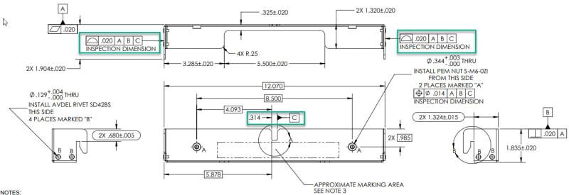
Here is the same engineer using the center of parallel FoS again on a sheet metal component. These surface profiles seem fully defined to me, as we assume C is a width datum feature again. Thoughts?

example_2_sa220i.jpg
 
Status
Not open for further replies.

Part and Inventory Search

Sponsor