Continue to Site

Eng-Tips is the largest engineering community on the Internet

Intelligent Work Forums for Engineering Professionals

  • Congratulations KootK on being selected by the Eng-Tips community for having the most helpful posts in the forums last week. Way to Go!

Profile of a line UZ- CZ in same drf 1

Status
Not open for further replies.

tainest77

Materials
Mar 8, 2020
12
Hello everyone,
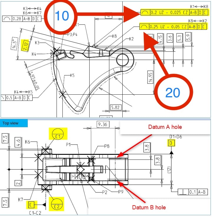
Would someone help please with the two highlighted line profiles on the attached drawing. (1) Is this intended to be one result and two tolerances or two results--one for each tolerance. (2) Provided that A-B datum is 3Dline between the two mounting holes (one on the other side). D datum is mid plane constructed from both main faces of this part. C datum is 3Dline as shown on attached. I already constructed the 3Dcurves from which these 2 line profiles will derive. Also what's the 2.12 and the 14.5 angle implication on this--Do I must use them? And by the way this is as per ISO standard. Big thanks to all.
2022-02-02_23h27_44_qldpkh.png
 
Replies continue below

Recommended for you

The profile tolerance is between points K1 to K8 for one surface and K8 to K2 for the other surface. So,consequently you will have to different surfaces and two different tolerances and, again, two different reported values.

The TED's you asked 2.12 and 14.5 degrees angle are needed to orient and locate the tolerance zones in relationship with the datums.

 
3FA8194D-5AE7-41A0-B57D-14D8EF15AD41_axorfq.jpg

CLARIFICATION:
Let’s focus on line profile #10 (#20 should be same): because of the two tolerances in the callout, one under UZ and one under CZ, does this means the line profile#10 needs to be evaluated and reported twice: one under UZ tolerance and one under CZ tolerance? Or only once for both tolerances?.
 
Do you know what UZ means?
Also the same question: do you know what CZ means?

If yes, please explain YOUR understanding....then we can move forward.
 
Thanks greenimi. Based on my modest knowledge, bothe UZ and CZ are ISO STANDARDS. “CZ” stands for common zone. Indication that multiple features in separated positions are deemed as a single tolerance zone.
The “UZ” modifier is used when you need to define a profile tolerance zone that is unequally disposed about the true profile of a surface.

 
Yes, you are almost correct, meaning here CZ= combined zone (per the latest ISO standards)
I don't think CZ plays any roles in your shown / actual drawing (no real use) because the profile constrains all non-redundant degrees of freedom, hence I don't think CZ has any value added/ benefit.
And more one more thing, I think the correct syntax here should be profile |0.2 CZ UZ -.025|......--but that's another story.
I still maintain that you need to report two values: a single value for the profile "10" and another single value for profile "20"
By the way, I do not know if ISO has any reporting standards, but ASME does: ASME Y14.45-2021 and this new standard could be very usefull for you when you decide what to report and how many values for each callout/ tolerance indicators.

 
Status
Not open for further replies.

Part and Inventory Search

Sponsor