Continue to Site

Eng-Tips is the largest engineering community on the Internet

Intelligent Work Forums for Engineering Professionals

  • Congratulations KootK on being selected by the Eng-Tips community for having the most helpful posts in the forums last week. Way to Go!

MMB / LMB sizes

Status
Not open for further replies.

greenimi

Mechanical
Nov 30, 2011
2,259
IF (again IF)
datum features B and C are to be modified at MMB or LMB
and
Note 3 is changed to "DRAFT ADDS MATERIAL"

what would be the appropriate sizes of the applicable boundaries? (sizes of datum feature simulators)
(from ASME Y14.8-2009)

MMB(B)=? MMB(C)=?
LMB(B)=? LMB(C)=?
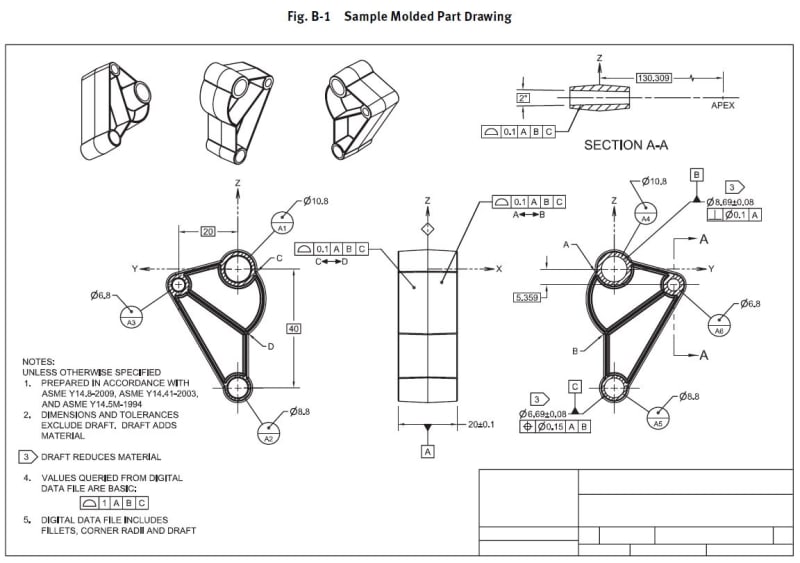
QFET_xp6w7j.jpg
 
Replies continue below

Recommended for you

No one would like to take up this challange? I don't have a correct answer, just curious about opinions.

 
We already have note 2, which seems to answer the question.

John-Paul Belanger
Certified Sr. GD&T Professional
Geometric Learning Systems
 
So which are the answers?
MMB for B is how much?
 
greenimi, the answer is that had note no. 3 not been specified, these datum features would not be appropriate to be applied at MMB over the inability to calculate the boundary due to "lack of control".

See the caution note in the end of para. 3.6.1 in ASME Y14.8-2008:

The standard said:
CAUTION: The symbols for “+DFT” and “–DFT” or “DRAFT ADDS MATERIAL” or “DRAFT REDUCES MATERIAL” should not be used for critical features due to the limitations of
(a) measurements being only near, rather than at, a given end of the feature
(b) the lack of control over the rest of the feature geometry
For critical features, a geometric control such as a profi le of a surface tolerance should be used.
 
What I meant in my reply is that note 2 tells us that any draft is totally ignored in your GD&T calculations, so the MMB (for B) would be 8.51.
If you want to include the draft idea into the MMB/LMB calculations -- which might be a worthy academic discussion -- you'd have to change the notes, but that still leads to the problems mentioned by Burunduk.

John-Paul Belanger
Certified Sr. GD&T Professional
Geometric Learning Systems
 
Just for my understanding. I have done molds. I have never seen notes before indicating "Draft adds/removes material".
Is this standard for the mold vendor? If it's in a ASME standard, I will look it up.
I have used the +DFT and -DFT, but as ref.
Note 5 is not needed.

Chris, CSWP
SolidWorks '20
ctophers home
SolidWorks Legion
 
Chris,
See Y14.8-2009 ¶3.6.1 Methods for Specifying Dimensions Affected by Draft
(latest edition I have access to)

"Know the rules well, so you can break them effectively."
-Dalai Lama XIV
 
ctopher said:
Is this standard for the mold vendor? If it's in a ASME standard, I will look it up.
I have used the +DFT and -DFT, but as ref.
Note 5 is not needed.

If you want to use -DFT or +DFT I am fine with that and my inquiry and questions on how to calculate MMB's, LMB's stay the same.

Belanger said:
What I meant in my reply is that note 2 tells us that any draft is totally ignored in your GD&T calculations, so the MMB (for B) would be 8.51.

J-P,

If this is the case then the datum feature simulator values (for those internal holes) will be bigger than the values allowed for the size+draft specifications therefore, the part might not fit into the applicable gages....Am I right?
So, how we can circumvent this issue?

 
Greenimi, yes it seems that the simulator may be larger than the physical boundary of the hole (since material is added).
Two things I would say... first, the Y14.8 standard does recognize that draft angle and tolerance "may exceed the perfect form boundary at MMC" unless otherwise specified (para. 3.6). That's not a direct answer to your issue, but they acknowledge that draft throws a wrench into the ideal mathematics.
More to your question, though, the caution that Burunduk already quoted seems to be the solution: "For critical features, a geometric control such as a profile of a surface tolerance should be used."


John-Paul Belanger
Certified Sr. GD&T Professional
Geometric Learning Systems
 
(2009) 4.11.6.3 - Clarifying Applicable MMB - In cases where the boundary is not clear, or another boundary is desired, the value of the boundary shall be stated, enclosed in brackets, following the applicable datum feature reference and any modifier in the feature control frame.

2018 covers this in section 7.11.10 - Explicit Specifications of True Geometric Counterpart Boundaries.

If this was my design I would make my intended boundary clear my placing the value in brackets.
 
Status
Not open for further replies.

Part and Inventory Search

Sponsor