Eng-Tips is the largest engineering community on the Internet

Intelligent Work Forums for Engineering Professionals

  • Congratulations waross on being selected by the Eng-Tips community for having the most helpful posts in the forums last week. Way to Go!

Stability of Main Trusses 3

Status
Not open for further replies.

Italo01

Structural
Sep 4, 2021
169
BR
Hello,

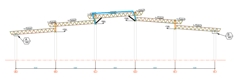
I'm designing a Steel Roof for a Gymnasium and the geometry required by the architect is a bit unusual. The Structure consist of 4 Main Trusses(32.5m Span and 9.32m tributary area) supporting secondary trusses. The problem arises because the roof has 5 different slopes( 2 towards one side and 3 towards the other). See the Elevation.

Eleva%C3%A7%C3%A3o_b6ockw.png


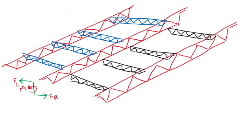
Because the different slopes, the upper chord of the exterior Main Trusses is connected do the Lower chord of the central trusses. I'm worried about a torsional instability of the central main trusses in which they buckle together like described by the blue lines in the figure below. So I decided to introduce large Fly Braces(Black Lines).
Eleva%C3%A7%C3%A3o_Instabilidade_cc4vy5.png


I would like to know if someone here has had some similar situation and if there's another solution more adequate than the fly braces.
PS: Because the length of the fly braces i'd use channel sections and not angles.
3D_m6g9ej.png


Thanks in advance.
 
Replies continue below

Recommended for you

Surely you can come up with a more attractive solution than fly braces. The architect will hate them!
 
One option would be to make the steel stub columns flexurally continuous with the columns below such that they cantilever from those columns. You could also to the reverse and moment connect the stub columns to the truss. Based on what you've shown us so far however, this might not suite the detailing look that you're going for.
 
why not make the vertical "orange" connectors tied into both the upper and lower chords of each truss, such that they transmit moments between the trusses?
 
I agree with KootK here, essentially extend your columns up as "cantilever" elements from low to high diaphragm. How are you anticipating the lateral system working for this? It appears you have x bracing in the roof, but not sure you have enough for the other direction without relying on a steel deck diaphragm or adding bracing in every bay. I would look at using a structural diaphragm or braced diaphragm at each step and making it stiff enough to spread the load to the end wall lateral system and then I could see the unbraced length being reduced significantly for the bottom chord of the deep truss.
 
Kootk, they are not steel columns, they are concrete columns(I forgot to mention). Since i'm designing only the steel roof, i did the model using only concrete columns and not the concrete beams. The truss chord is connected to the columns with a base plate.

SWcomposite, this would be ideal but unfortunately, the architect wants this way.

Aesur, i think that is a good idea.
 
What is your lateral force resisting system? Are you in a high seismic area?
 
your system should be reversed [long span frame to be short span]

01_pb54ts.jpg
 
adn26 said:
your system should be reversed [long span frame to be short span]
I don't follow what you said, could you better describe what you are saying?
 
Italo01:
The way I see it, you have something akin to the following, which makes up a two way gridwork of trusses. You have the simple span ‘Main Trusses,’ 32.5m (106.6') long, maybe 8, 9 or 10' deep; with six sets of five ‘secondary trusses,’ each 9.32m (30.6') long, equally spaced at (106.6'/5 = 21.32') along the Main Trusses, and imparting the major gravity point loads to the Main Trusses. At each of these six secondary truss grid lines, the Main Trusses should have a major vertical web member which picks up moments and gravity loads from an upper and lower secondary truss. The secondary trusses are then infilled with std. 21.3' long stl. jsts. and metal decking. The short exterior canti. ends on the secondary truss grid lines are separate short trusses which may be fixed to the Main Trusses, on the ground and then lifted with the Main Trusses onto the conc. end columns. You will have to provide significant diaphragm chord members to each Main Truss at the edges (east and west edges) of each of the roof deck planes to get the diaphragm loads into the Main Trusses and to the ground. You could sub-assemble three of the roof deck panels (north, middle and south), that would be two edge secondary trusses (north and south), the 21.3' long stl. jsts., and most of the roof decking, on the ground and lift these panels into place on the Main Trusses. Then, the other two panels in that plane would be infilled with 21.3' long stl. jsts. and roof decking from above. While you may not be responsible for the conc. columns, foundations, etc., it’s a long way from the roof to the ground, and someone better be thinking about how the roof loads are going to get to the foundations. You guys better be talking, as a team, how this whole thing is going to work, because each group’s actions and design decisions has a great influence on what the next group can or has to do. If they sub-divide the responsibility much more/further on these jobs, nobody will really responsible for anything but their own 8' piece of angle iron, wherever it goes and whatever its loading.
 
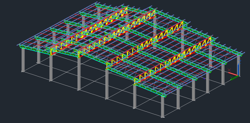
I assume that the 3D figure in the first post is from some kind of analysis software. Have you performed a buckling analysis to see what happens in the structure when it buckles?

One way to add stability could be to connect the horizontal bracings you have on the sides. If you add bracings between the two top main trusses that might stiffen the structure. That would create an H-shaped horizontal bracing.
 
Dhengr, could you explain what those abbreviations mean(or someone else) so i can understand everthing?

"The secondary trusses are then infilled with std. 21.3' long stl. jsts. and metal decking."

Since i don't live in a english speaking country, i'm not used to the abbreviations.

Thank you so much.
 
ThomasH, i will perform a buckling analysis.

I just think that, since the web consist of double angles(with intermediary welded angles between), the lateral stiffness of the of the structure may be overestimated in the analysis.

Should i find the equivalent moment of inertia considering it as a sort of a viereendel truss, like the eurocode does for built-up columns or am i overthinking?
 
std. 21.3' long stl. jsts.
standard 21'3 foot long steel joists

As mentioned above, are you making the long-to-short truss connections moment carrying by using those vertical members in the main truss at those locations?

Would it help to make the short trusses line up instead of being staggered?
 
Yes, IFRs, the connections are moment connections. The short trusses are lined on the vertical plane.
 
Thank you all for the inputs. I'm sorry for the late response but i've been working on other projects and couldn't do the analysis soon. I introduced the bracings suggested by ThomasH, and corrected the stifness of the webs and performed the buckling analysis. The suggestion improves considerably the overall stiffness of the structures and the buckling analysis was satisfactory.

I'd like to ask suggestions of books about roof steel structures written in english, because this is a topic that i've never studied in english and have some difficulty with the nomenclature. Every time that has a eng-tips thread on roof structures i get a little bit lost on the discussion.

 
Status
Not open for further replies.

Part and Inventory Search

Sponsor

Back
Top