Continue to Site

Eng-Tips is the largest engineering community on the Internet

Intelligent Work Forums for Engineering Professionals

  • Congratulations KootK on being selected by the Eng-Tips community for having the most helpful posts in the forums last week. Way to Go!

Inlet Geometry 2

Status
Not open for further replies.

TugboatEng

Marine/Ocean
Nov 1, 2015
11,445
Background: I have an engine that I've received into my fleet that smokes at full power. These engines are essentially new and confirmed to be in good operating condition by the manufacturer. Everybody else's stumped so I get to take my turn at it.

What I have found is that the engine is installed very close to the after bulkhead of the engine room and the air filter box was modified to fit in this space. During the modification, the radiused inlet to the turbocharger was removed to space constraints. It is my belief that the squared off entry is choking the turbocharger for air.

Now I need to figure out how to correct this issue with limited space. I thought about projecting the inlet pipe into the air box and flaring the end of it. Much like a velocity stack on an old carburetor.

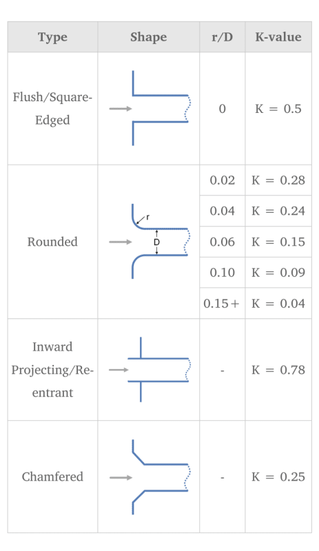
However, this reentrant geometry may also provide the worst k factor.
Screenshot_20231218-142107_nzl2ni.png
 
Replies continue below

Recommended for you

Is it getting sufficient oxygen at full power?

-----*****-----
So strange to see the singularity approaching while the entire planet is rapidly turning into a hellscape. -John Coates

-Dik
 
It is a smoking black so the assumption is no.
 

Was the original air filter box 'radiused' and if so, by how much? Even with a slight radius, the K value is nearly cut in half. That would likely cause the lack of air... since it is unlikely the original design 'smoked'. Can you compare it to a setup that has a proper filter box?

-----*****-----
So strange to see the singularity approaching while the entire planet is rapidly turning into a hellscape. -John Coates

-Dik
 
Can we get a picture, please?

Can the air filter housing be modified/raised and stack a second or third air filter (double/triple the filter area). I’m wondering (don’t know) you might be able to reduce the pressure drop at the filter and recover what you gained by removing the radius at the inlet.

Good Luck,
Latexman

 
This is an EMD 8-710 engine.

The air filter housing as supplied by the engine manufacturer was a box with bag type filters, inline flow configuration with a radiused edge into the outlet duct.

The housing has been cut in half to make a T shape. The bag filters are on the ends and the outlet in the middle. The outlet duct is welded directly to the side of the housing with no radius.

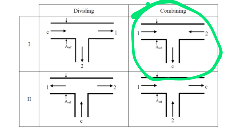
I also suspect their may be issues with two direction flow converging in the T.

I will try to visit the engine tomorrow for pictures.

This is my flow situation:

Screenshot_20231218-205712_rygi8c.png
 
You're correct in that square edge and opposing flows are going to increase pressure drop compared to radiused fittings.

Until we can see what space you have by drawings or pictures it's difficult to comment on any better configuration, but anything with radius or bends would be better than what you seem to have. Maybe even guide vanes inside the tee.

Remember - More details = better answers
Also: If you get a response it's polite to respond to it.
 
Pictures of the actual installation, and a sketch/drawing of the original factory recommendation would be wonderful! Then we could noodle on what you have, compared to a "standard" that (is supposed) to work.

Good Luck,
Latexman

 
I looked up some pictures and that's a big old engine alright, but couldn't really see what the "normal" air entry system looked like.

Remember - More details = better answers
Also: If you get a response it's polite to respond to it.
 
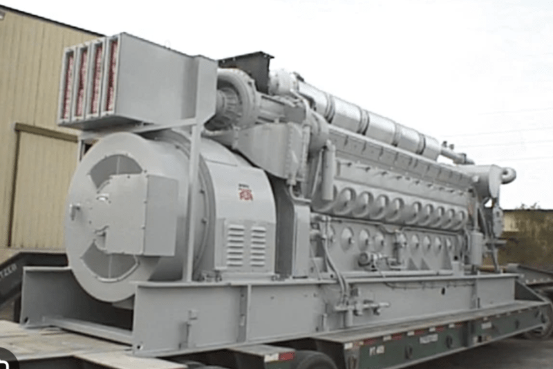
Here is the standard configuration. Air filter is the box on left side with red colored slots (those are the bags). I am flying down there now and will try to get on the boat if it's available.

Screenshot_20231219-041211_snjk6s.png
 
Judging by the "standard" configuration, there should not have been a need to adjust the air intake. You'd need just as much (if not more) clearance between the bulkhead and both the conduit box (grey box at lower right below air filters) and the air inlet for the generator (open vaned area below the filters). Ballpark guess is that the generator manufacturer specifies something like 3 feet to allow sufficient flow at the air intake region. Conduit box should have a minimum 30 inch clearance (or the door swing, if that's larger).

Converting energy to motion for more than half a century
 
Why wasn't a test run done in the seller's store?.

Regards
 
"What I have found is that the engine is installed very close to the after bulkhead of the engine room and the air filter box was modified to fit in this space. During the modification, the radiused inlet to the turbocharger was removed to space constraints."

TugBoat will have the rest of the story, just getting that engine in a existing engine room is more than a challenge.
 
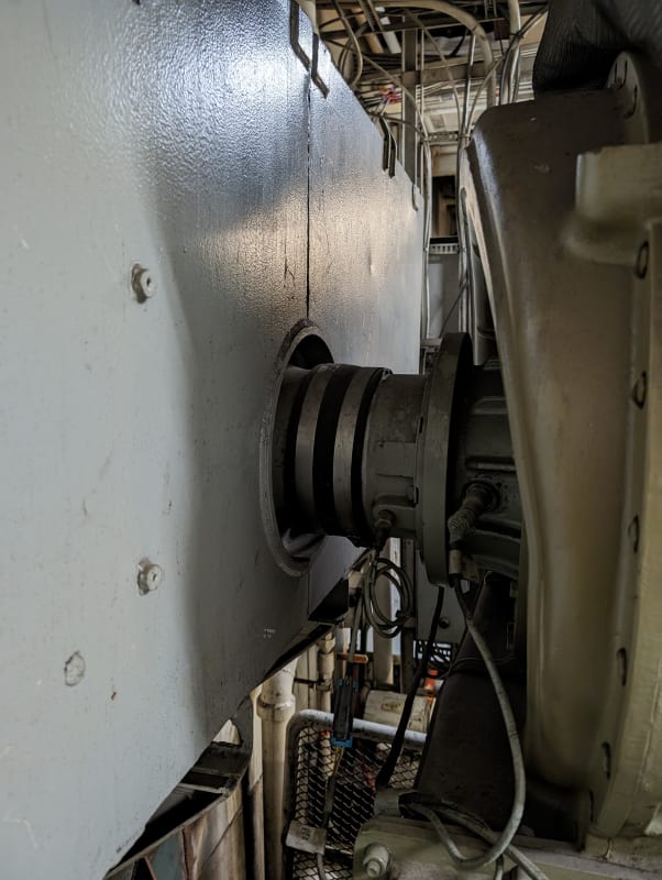
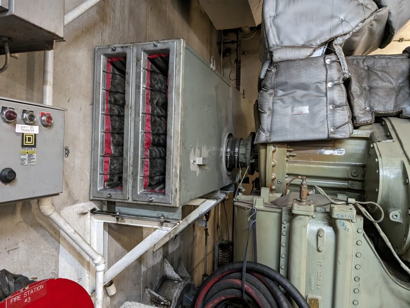
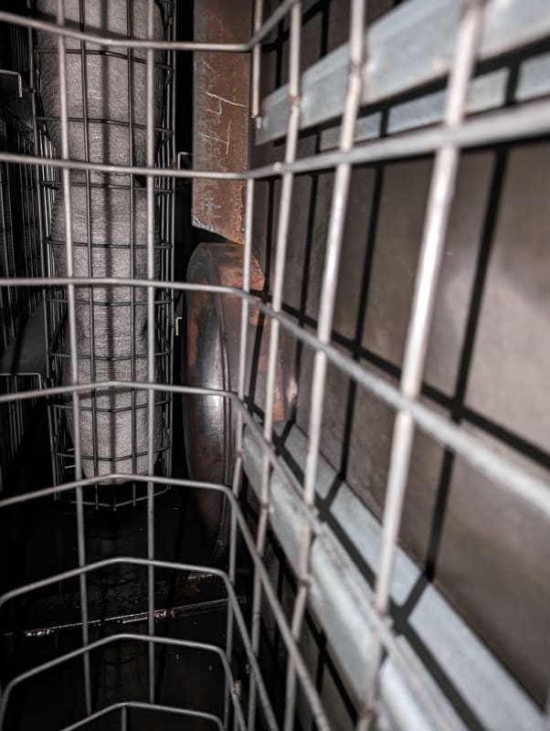
Got 'em. First pic shows external duct into turbo. Second pic shows clearance issue. Filter box is mirrored on other side. Third pic shows there is indeed a radius but it is raised off surface. Diameter of inlet is a about 8"

PXL_20231219_175231762_tdrnjf.jpg
PXL_20231219_175318201_y8rgib.jpg
PXL_20231219_182751977_f9w3fq.jpg
 
Third pic shows a rounded Inward Projecting/Re-entrant. Idk the K for that, but I suspect it’s closer to 0.78 than 0.28. And, the air has to turn 90[sup]o[/sup] compared to the factory straight through flow path. That’s more K and not in the direction of goodness.

Good Luck,
Latexman

 
Higher, as flow is significantly more disturbed in 3D. You are essentially losing a 50% of volume in the approach path to the entry area cut off by the wall. It would look like half of the first diagram, where the bottom side of the outlet is a long horizontal line.

It's like attaching a horizontal discharge nozzle of a tank with the bottom at floor elevation.
To get full possible discharge, the nozzle must be located some distance above the tank floor. I'd estimate 2D above the floor.

--Einstein gave the same test to students every year. When asked why he would do something like that, "Because the answers had changed."
 
Ok, a few questions and some things /i guess you are already doing.

Was that unit supplied by the engine manufacturer or does it look "home made"?

These engines intake a vast amount of air, but appear to have been originally designed for railway use. Is there enough free air entering the engine room?
Even a small decrease in air pressure would impact performance. Do you or can you measure air pressure in the engine room?

The turbos themselves seem to be a hybrid turbo / blower up to half throttle. Is that correct on this unit? Does the turbo actually work properly?
What is the length / diameter of the exhaust duct? Remember these were designed for railway use with very short exhausts so any back pressure will kill the engine just as well at full throttle.

Is all that lagging cooking your turbo?

One thing to maybe try is to increase the space of the plenum by adding two rectangular sections in the middle to create a bigger chamber. I think there might be an issue with the further two air filters not providing as much air as the inner two. A more central position would help if left as a single entrance.

At the same time make the air connection to the engine smooth with the wall like Latexman alludes to.

Or maybe extend the bottom section all the way as a half pipe?


Remember - More details = better answers
Also: If you get a response it's polite to respond to it.
 
It is difficult to get the perspective, but it appears to me that the filter bag we see in the third picture is masking off half the exit duct. I suspect it would be better to entirely remove the inward projecting nozzle for the exit air. When air is flowing through the unit, the bag will be sitting hard against the cage and mask off even more of the flow area.

Katmar Software - AioFlo Pipe Hydraulics

"An undefined problem has an infinite number of solutions"
 
I think it is likely that the air entering the nozzle is vortexing at high speed. Like water going down the drain in a bath tub. That would greatly increase the pressure drop.
 
Status
Not open for further replies.

Part and Inventory Search

Sponsor