Continue to Site

Eng-Tips is the largest engineering community on the Internet

Intelligent Work Forums for Engineering Professionals

  • Congratulations SSS148 on being selected by the Eng-Tips community for having the most helpful posts in the forums last week. Way to Go!

Theoretical Question - Planar Truss Problem 2

comhedoisl

Mechanical
Apr 9, 2020
4
Hi all.

This is an interesting theoretical question from a book of Feodosiev - Advanced Stress and Stability Analysis. It reads like this:

"A plane truss consisting of n>2 equal and equally spaced rods, connected in a common node, O.
The force P acts in the plane of the truss.
Show that the displacement of the node O is always directed along the force P and that the value of this displacement does not depend on the angle /alpha."

The book does provide an answer to this problem, but not with enough detail -- at least from my point of view. I'd like to have a more detailed discussion on this problem with other folks. Could you help me providing your insights?

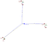
**the blue circle is not part of the structure

1744903299358.png

Thanks.
 
Replies continue below

Recommended for you

A quick check through, I may be missing something:
First, you have to assume "small deflections". Let x be the angle between force P and the spoke in question.
In that case, the deflection in each spoke will be cos(x) times the deflection in the direction of the force, and the component of force in each spoke, parallel to the force P, will be proportional to (cos(x))^2. Adding up the cosine-squared for N equally spaced spokes will give a constant, regardless of angle alpha. Example: Adding cosine squared for 20, 140, and 260 degrees is same as adding cosine squared for 30, 150, and 270 degrees, etc.

And, adding up the components of those same forces perpendicular to the force will give a cos(x)*sin(x) term for each spoke. And adding cosine x sine of 20, 140, 260 degrees gives zero. IE, the component of the spoke reactions normal to force P total up to zero, so deflection and force are always aligned.
 
You can use vector algebra . Lets assume ( for simplicty ) n=4
In this case , the angles btw the spokes will be 90 degr. Then define a Cartesian coordinate system having the origin is at pt. O and , X and Y axis matching to the spikes.
Then define a force F having random angle ( α ) with X and find the components Fx and Fy.
-Fx is resisted by spikes on the X axis and one will have tension Fx/2 and the other compression Fx/2 and total displacement will be ( δx ) and for lineer elastic rods will be proportional to Fx taht is axial stiffness of the rod K= E*A and Fx= K*δx ,
-Fy is resisted by spikes on the Y axis and one will have tension Fy/2 and the other compression Fy/2 and total displacement will be ( δy) and for lineer elastic rods will be proportional to Fy that is axial stiffness of the rod K= E*A and Fy= K*δy ,
- Then draw the displacement vectors and find the resultant δ , which will have the same direction with force F .
Important point is ,number of spikes n must be at least 3. If n=2 , and the load is not parallel to spikes ,the system will be geometrically nonlinear ( although the spikes are lineer elastic )and the final displacement will not be parallel and proportional with the force .
 
Last edited:
Thank you all for your inputs.

The question does not mention about small deflections, but I think it just take it for granted. This assumption should be taken if needed.

It also feels right that the deflection should be in the direction of the force P. I just couldn’t properly explain (in detailed steps) why.

A quick check through, I may be missing something:
First, you have to assume "small deflections". Let x be the angle between force P and the spoke in question.
In that case, the deflection in each spoke will be cos(x) times the deflection in the direction of the force, and the component of force in each spoke, parallel to the force P, will be proportional to (cos(x))^2. Adding up the cosine-squared for N equally spaced spokes will give a constant, regardless of angle alpha. Example: Adding cosine squared for 20, 140, and 260 degrees is same as adding cosine squared for 30, 150, and 270 degrees, etc.

And, adding up the components of those same forces perpendicular to the force will give a cos(x)*sin(x) term for each spoke. And adding cosine x sine of 20, 140, 260 degrees gives zero. IE, the component of the spoke reactions normal to force P total up to zero, so deflection and force are always aligned.
JStephen, I like the reasoning, it seems right, but it still gives me some questions…

— “the component of the spoke reactions normal to force P total up to zero”… Wouldn’t that be the case from the start, considering that the resultant of the forces from the spokes should be directly oposite from P, for equilibrium? I’m not sure how to go from this to “deflection and force are always aligned”.

— “the deflection in each spoke will be cos(x) times the deflection in the direction of the force”… Let’s call Delta_P the deflection in the direction of the force P. So, Delta_P*cos(x) is the component of the Delta_P in the direction of the spoke. In the end, Delta_P will be indeed the full displacement of point O, but how to conclude that from the above?

You've drawn a bicycle wheel, so the empirical answer is yes.
Right. As I mentioned, it seems right the displacement is in line with the load in this case. But how to really prove that generally is the trick part for me…

You can use vector algebra . Lets assume ( for simplicty ) n=4
In this case , the angles btw the spokes will be 90 degr. Then define a Cartesian coordinate system having the origin is at pt. O and , X and Y axis matching to the spikes.
Then define a force F having random angle ( α ) with X and find the components Fx and Fy.
-Fx is resisted by spikes on the X axis and one will have tension Fx/2 and the other compression Fx/2 and total displacement will be ( δx ) and for lineer elastic rods will be proportional to Fx taht is axial stiffness of the rod K= E*A and Fx= K*δx ,
-Fy is resisted by spikes on the Y axis and one will have tension Fy/2 and the other compression Fy/2 and total displacement will be ( δy) and for lineer elastic rods will be proportional to Fy that is axial stiffness of the rod K= E*A and Fy= K*δy ,
- Then draw the displacement vectors and find the resultant δ , which will have the same direction with force F .
Important point is ,number of spikes n must be at least 3. If n=2 , and the load is not parallel to spikes ,the system will be geometrically nonlinear ( although the spikes are lineer elastic )and the final displacement will not be parallel and proportional with the force .
That’s correct, but it’s not general… Considering 4 rods, the deflection of each rod (in the direction of the corresponding rod) is dependent on the angle, but the full displacement is not (you end up in a sum of sin2(x) with cos2(x)… I couldn’t work things out yet for 5 rods…

Suggest to use strain energy method
I’ll try that… I tried before like the following, but could not go further and conclude that the deflection is in the direction of P and its value does not depend on the angle…

For a truss with N rods, Strain energy U will be:
U = sum( (F_i^2) * L / (2EA) ), with i from 1 to N

From here, I could differentiate U with respect to P, and find the displacement in direction of P… but from here, how to conclude that this is the full displacement of the node O?

Thanks again for your insights.
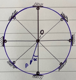
 
"A plane truss consisting of n>2 equal and equally spaced rods, connected in a common node, O.
By definition, the rods are identical and equally spaced. The angle btw the rods for 3 rods , 120 degr, four rods ,90 degr. so on. The displacement of point O will be in the direction of the force .
 
The displacement of point O will be in the direction of the force .
That’s what the exercise want us to prove or show why.

The full displacement of a node in a truss do not always follow the direction of the force applied to that node.

Why would that be the case in the truss from the example? Is it because of symmetry?

It seems to be related to symmetry in which the rods are disposed. From that it makes sense it would follow the load.

But how to show that, in general?
 
But how to show that, in general?
Forgive my brethren for being engineers rather than mathematicians, as this is more of a mathematical challenge than an engineering one. :giggle: I'm myself am also an engineer but I was once (at least by education) a mathematician, so I'll attempt to provide the steps that may lead you to a solution.

  1. This seems like a mathematical induction problem.
  2. Recognise that there are two main variables here and n and α. Proving n>2 is probably the harder part
  3. Give each aspect their algebraic variables and crunch the formulas. (eg let stiffness of the rods=k, you have P, α & n)
  4. Prove that the displacement vector (magnitude and direction) is independent of α when n=3
  5. Prove that displacement vector (magnitude and direction) is independent of α for the variable n+1.
  6. Through proof by induction it the answer follows.
    • (Specifically if it is true for n=3 and true for n+1, then it follows that it must be true for all values n≥3. (aka for n>2)
Simple to write. Maybe less simple to do. Crunch the variable and hopefully watch them drop out as necessary.
 
Last edited:
I’ll try that… I tried before like the following, but could not go further and
The problem is complicated mostly because there is multiple statical indeterminacy. Also the members need to be pretensioned as compressive loads may lead to buckling. But may be we can neglect buckling.

However, it will be more convenient to use FEA.
 
Preload doesn't affect the deflection if you (rightly) ignore buckling, it just adds a DC offset to the stresses. That is, yes it it is a real world consideration but an unnecessary complication for this question. Incidentally although a spoked wheel seems relevant, a real bicycle wheel works in a much more complex fashion, as the rim distorts it stretches the horizontal spokes.
 
Jstephen has pretty much answered it.

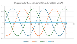
The displacement aligns with the applied force P because, with equally spaced rods, the perpendicular (sideways) force components cancel out. The 4-rod case is easy to understand intuitively, as each spoke has a directly opposing one, so their sideways pulls cancel exactly. It's the same with other numbers of rods; it's just less obvious by eye. But if you look at a chart of 3 rod version it's clear enough. No matter which direction the force points, the sum of the perpendicular components - which are functions of cosA sinA, sum to zero. That symmetry forces the node to move only in the direction of P. Forces aligned with P are all that's left.

1745281546277.png

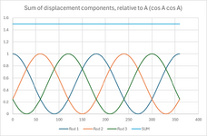
Then there's the question of why the displacement magnitude doesn't change with direction. This chart shows that the total stiffness in the direction of P is independent of angle. The deflection of each rod in the direction of P is a function of cosine squared. The sum of the cosine-squared components of all the rods always adds up to n/2, i.e. the deflection is always the same, no matter the angle. It’s directly analogous to 3-phase AC power, the evenly spaced phases ensure smooth, continuous output, unlike the pulsing of single-phase.

1745281909510.png
 
Last edited:
Preload doesn't affect the deflection if you (rightly) ignore buckling, it just adds a DC offset to the stresses. That is, yes it it is a real world consideration but an unnecessary complication for this question. Incidentally although a spoked wheel seems relevant, a real bicycle wheel works in a much more complex fashion, as the rim distorts it stretches the horizontal spokes.
I disagree with this from two aspect.

Preload clearly can increase deflection It is a similar to preloading bolts or bicycle spokes.

Also regarding a bicycle when the 'stretching' of spokes horizontal or otherwise is negligible. The primary way a bicycle load path works is via a reduction in the pretension of the spokes local to the load point.

Again very similar to how preloaded bolts work. You are getting minimal increase in loads on bolts or spokes if they are pretensioned.
 
Oh and for what it is worth.
  • The problem has to assume non buckling for the problem to be valid as presented as buckling would introduce non-linearity.
  • The problem as presented (n>2) I believe necessitates compression in the rods. If the rods are say cables with tension only then (n>3) I believe would be true.
 
If it is a linear analysis you can use superposition to show that the preload makes no difference.
True. I was wrong in that aspect of my post. I agree with your logic.

I did consider the that superposition logic. But I dismissed it due to the bolt 'preload logic'. But bolt preloading is non-linear. It is extremely stiff until preload is lost. In this circumstance that nonlinearity doesn't apply as you correct point out.
 
Thank you all for the good discussion.

Jstephen has pretty much answered it.

The displacement aligns with the applied force P because, with equally spaced rods, the perpendicular (sideways) force components cancel out. The 4-rod case is easy to understand intuitively, as each spoke has a directly opposing one, so their sideways pulls cancel exactly. It's the same with other numbers of rods; it's just less obvious by eye. But if you look at a chart of 3 rod version it's clear enough. No matter which direction the force points, the sum of the perpendicular components - which are functions of cosA sinA, sum to zero. That symmetry forces the node to move only in the direction of P. Forces aligned with P are all that's left.

View attachment 8533
Tomfh, I like the reasoning and seems pretty convincing, but I still want to understand something... Wouldn't this 'sum of perpendicular components sum to zero' always occur, no matter if the truss is symmetric or not? The resultant of the forces in node O will be aligned with force P, and opposite, for equilibrium.
 

Part and Inventory Search

Sponsor