Navigation
Install the app
How to install the app on iOS
Follow along with the video below to see how to install our site as a web app on your home screen.
Note: This feature may not be available in some browsers.
More options
Style variation
-
Congratulations MintJulep on being selected by the Eng-Tips community for having the most helpful posts in the forums last week. Way to Go!
You are using an out of date browser. It may not display this or other websites correctly.
You should upgrade or use an alternative browser.
You should upgrade or use an alternative browser.
30*C AC Wire Resistance 4
- Thread starter Mbrooke
- Start date
- Status
- Not open for further replies.
- Thread starter
- #61
@Stevenal- on thermal trip that is correct. An equation with log or feed back starting at the actual conductor temperature is much more accurate. However for those calculating EFLI in the field in much easier to just use the final conductor short circuit temperature or there about.
5 or 10 second disconnection times with EGCs and tap conductors could actually have me using 150*C (THHN) and 250*C (XLPE) conductor temps.
5 or 10 second disconnection times with EGCs and tap conductors could actually have me using 150*C (THHN) and 250*C (XLPE) conductor temps.
- Thread starter
- #62
Fischstabchen
Electrical
Faster tripping doesn't necessarily mean less energy.
- Thread starter
- #64
- Thread starter
- #65
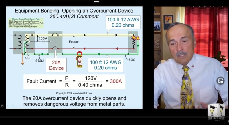
An example of where high ground fault loop impedance may result in hazard to life and property based on Preece fusing current-
As applied to breaker time current curves:
10 gauge EGC 333 amps / 60 = 5.55
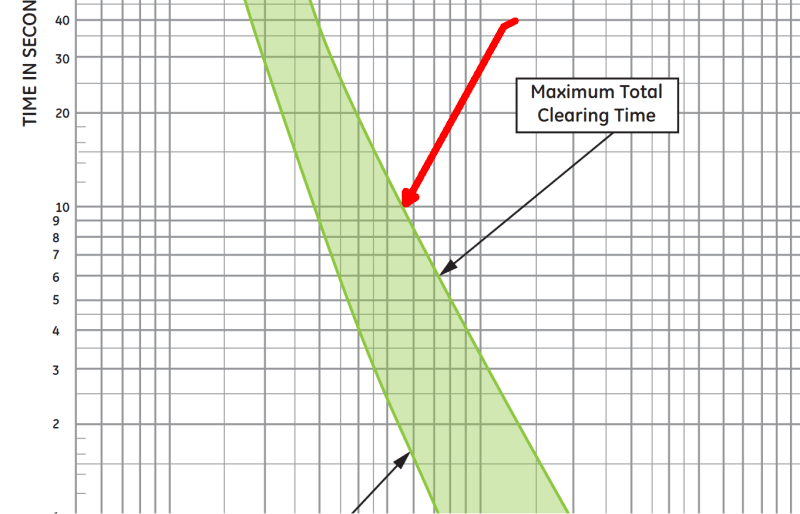
8 gauge wire 472 amps divided by 100 = 4.72
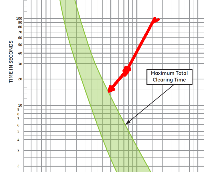
6 gauge wire 668 amps divided by 200 = 3.34
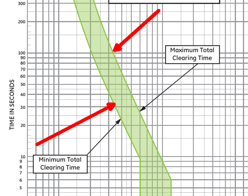
A 60 amp circuits will result in the EGC melting under acceptable worse case breaker clearing times, a 100 amp circuit has a 50% chance of the EGC melting before the breaker opens and a 200 amp circuit has a 100% chance of the EGC melting (breaking the the path back to the source) before the breaker ever opens.
Based upon these time current curves of a common brand name UL listed breaker one could make the inference that Table 250.122 assumes a clearing time faster than 10 seconds (and as such the intent {goal} of the code) is that a ground fault clear in less than 10 seconds.
As applied to breaker time current curves:
10 gauge EGC 333 amps / 60 = 5.55

8 gauge wire 472 amps divided by 100 = 4.72

6 gauge wire 668 amps divided by 200 = 3.34

A 60 amp circuits will result in the EGC melting under acceptable worse case breaker clearing times, a 100 amp circuit has a 50% chance of the EGC melting before the breaker opens and a 200 amp circuit has a 100% chance of the EGC melting (breaking the the path back to the source) before the breaker ever opens.
Based upon these time current curves of a common brand name UL listed breaker one could make the inference that Table 250.122 assumes a clearing time faster than 10 seconds (and as such the intent {goal} of the code) is that a ground fault clear in less than 10 seconds.
- Thread starter
- #66
Complementing the above, a lab example of delayed clearing with a 60 amp OCPD on 6mm2 (5.26mm2 = 10AWG) wire.
Smoking starts about 15 seconds after energization, breaker trips at about 40 seconds.
For a real world 60 amp circuit trip should not exceed 5 seconds. Going by a typical time current curve 480 amps is indicated for a 5 second trip giving a max Zs of 0.25 ohms at 120 volts and 0.577 ohms at 277 volts.
With all this said I would give anything for a research lab like this:
- Thread starter
- #67
Alright, back on topic.
Asking around we came up with a guess that at 30*C there would be multiplier of 0.823. At 30*C the AC resistance would be 17.7% lower.
Thus, we obtain:
14 AWG = 3.1 ohms per 1000 feet 75*C = 2.5513 ohms at 30*C
12 AWG = 2.0 ohms per 1000 feet 75*C = 1.646 ohms at 30*C
10 AWG = 1.2 ohms per 1000 feet at 75*C = 0.9876 ohms at 30*C
Here are the two equation that I am (mostly) basing my inferences on:
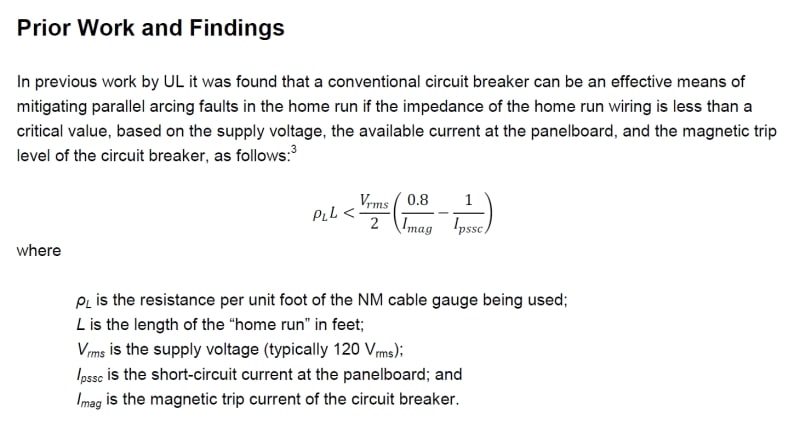
&
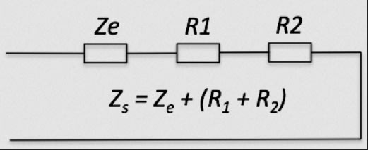
Some slight changes being that I am assuming 115 volts (lower end of the acceptable bandwidth) and that the fault current must be 125% over the breaker's minimum magnetic pickup as derived from the attached time current curves. Also I am not concerned with the "home run" instead the whole circuit to its furthest point but ending at cord caps and light fixture leads. 30*C vs 25*C in UL's research.
GFL = ground fault loop
15 amp breaker:
14-14 = 124.672 feet = 0.6361513472 ohms GFL =/= 188 amps at 120 volts, 179 amps at 114 volts
12-14 = 196.85 feet = 0.826238505 ohms GFL =/= 145 amps at 120 volts, 138 amps at 114 volts
10-12 = 314.961 feet = 0.8294812896 ohms GFL =/= 145 amps at 120 volts, 137 amps at 114 volts
20 amp breaker:
12-14 = 164.042 feet = 0.6885334866 ohms GFL =/= 174 amps at 120 volts, 166 amps at 114 volts
10-12 = 229.659 feet = 0.6048299424 ohms GFL =/= 198 amps at 120 volts, 188 amps at 114 volts
Assuming 2000 amps of fault current Line to Neutral at the panel board we obtain a Ze of about 0.05 ohms...
So adding 0.05 ohms to 0.8294812896 = 131 amps at 115 volts
Adding 0.05 ohms to 0.6885334866 = 156 amps at 115 volts
This is right up to 131 and 150 amps-
15 x 7 = 105 amps ==== 125% of 105= 131 amps (UL's parellel arc mitigating threshold)
20 x 6 = 120 amps ==== 125% of 120 = 150 amps (UL's parallel arc mitigating threshold)
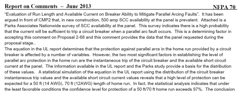
IMO, 500 amps (0.25 ohms Ze) at the panelboard is nowhere near as prevalent as its being argued in front of the code making panels. Further, I wish I could also test the magnetic pickup of modern breakers.
It is my opinion that both the external loop impedance and magnetic pickup of circuit breakers are being wittingly exaggerated in an effort to justify the mandate of AFCIs vs a practical table limiting the run length of 15 and 20 amp 120 volt residential circuits.

And yes, I know Table 68 in the CEC references voltage drop, but behind the scenes voltage drop is of the least concern to anyone involved.
Asking around we came up with a guess that at 30*C there would be multiplier of 0.823. At 30*C the AC resistance would be 17.7% lower.
Thus, we obtain:
14 AWG = 3.1 ohms per 1000 feet 75*C = 2.5513 ohms at 30*C
12 AWG = 2.0 ohms per 1000 feet 75*C = 1.646 ohms at 30*C
10 AWG = 1.2 ohms per 1000 feet at 75*C = 0.9876 ohms at 30*C
Here are the two equation that I am (mostly) basing my inferences on:

&

Some slight changes being that I am assuming 115 volts (lower end of the acceptable bandwidth) and that the fault current must be 125% over the breaker's minimum magnetic pickup as derived from the attached time current curves. Also I am not concerned with the "home run" instead the whole circuit to its furthest point but ending at cord caps and light fixture leads. 30*C vs 25*C in UL's research.
GFL = ground fault loop
15 amp breaker:
14-14 = 124.672 feet = 0.6361513472 ohms GFL =/= 188 amps at 120 volts, 179 amps at 114 volts
12-14 = 196.85 feet = 0.826238505 ohms GFL =/= 145 amps at 120 volts, 138 amps at 114 volts
10-12 = 314.961 feet = 0.8294812896 ohms GFL =/= 145 amps at 120 volts, 137 amps at 114 volts
20 amp breaker:
12-14 = 164.042 feet = 0.6885334866 ohms GFL =/= 174 amps at 120 volts, 166 amps at 114 volts
10-12 = 229.659 feet = 0.6048299424 ohms GFL =/= 198 amps at 120 volts, 188 amps at 114 volts
Assuming 2000 amps of fault current Line to Neutral at the panel board we obtain a Ze of about 0.05 ohms...
So adding 0.05 ohms to 0.8294812896 = 131 amps at 115 volts
Adding 0.05 ohms to 0.6885334866 = 156 amps at 115 volts
This is right up to 131 and 150 amps-
15 x 7 = 105 amps ==== 125% of 105= 131 amps (UL's parellel arc mitigating threshold)
20 x 6 = 120 amps ==== 125% of 120 = 150 amps (UL's parallel arc mitigating threshold)
IMO, 500 amps (0.25 ohms Ze) at the panelboard is nowhere near as prevalent as its being argued in front of the code making panels. Further, I wish I could also test the magnetic pickup of modern breakers.
It is my opinion that both the external loop impedance and magnetic pickup of circuit breakers are being wittingly exaggerated in an effort to justify the mandate of AFCIs vs a practical table limiting the run length of 15 and 20 amp 120 volt residential circuits.


And yes, I know Table 68 in the CEC references voltage drop, but behind the scenes voltage drop is of the least concern to anyone involved.
-
1
- Thread starter
- #68
Supporting (quoted) Docs-
UL:
NFPA 2012 ROM:
NFPA Public Input Report for the 2023 NEC which includes testing done by Legrand:
UL:
NFPA 2012 ROM:
NFPA Public Input Report for the 2023 NEC which includes testing done by Legrand:
- Status
- Not open for further replies.
Similar threads
- Replies
- 8
- Views
- 903
- Question
- Replies
- 1
- Views
- 2K
- Locked
- Question
- Replies
- 0
- Views
- 2K
- Question
- Replies
- 12
- Views
- 18K
- Locked
- Question
- Replies
- 8
- Views
- 6K

