Navigation
Install the app
How to install the app on iOS
Follow along with the video below to see how to install our site as a web app on your home screen.
Note: This feature may not be available in some browsers.
More options
Style variation
-
Congratulations TugboatEng on being selected by the Eng-Tips community for having the most helpful posts in the forums last week. Way to Go!
You are using an out of date browser. It may not display this or other websites correctly.
You should upgrade or use an alternative browser.
You should upgrade or use an alternative browser.
30*C AC Wire Resistance 4
- Thread starter Mbrooke
- Start date
- Status
- Not open for further replies.
- Thread starter
- #21
You will never know the source impedance with a sufficient degree of accuracy for any of those to ever matter.
David, can we agree to disagree?
![[smile] [smile] [smile]](/data/assets/smilies/smile.gif)
davidbeach
Electrical
Not going to bother watching it. You can very precisely measure it right this instant, but tomorrow it will be different. Probably doesn't even take that long, just wait for the next operation of the nearest LTC. If you're far from generation the source impedance is more stable in that it's mostly wires and transformers; close to generation it matters what's running and what isn't. Really close to generation and it matters how early in the fault you are. Utilities switch stuff. All. The. Time. Every switching operation changes source impedance. Knock yourself out calculating all the permutations and combinations. It's truly a fools errand, but welcome to it.
I’ll see your silver lining and raise you two black clouds. - Protection Operations
I’ll see your silver lining and raise you two black clouds. - Protection Operations
- Thread starter
- #23
David, it might be a fools tail spin but UL, Leviton and Eaton have been obsessing over it for three decades now Geneva Switzerland aside. To them it matters very much and to me more so considering its being used to drive earth shaking code rules every 3 years.
Second LTC varients and SCADA recloser switching aren't going to effect the source impedance to the point R1 + R2 of final circuit will not dominate. Truth is 30*C vs 75*C R1+R2 will make on orders of magnitude more impact in a long circuit than a Ze of 0.35 or 0.15 ohms.
So my original question still holds water in spite of what I already calculated.
this should be universal>>>
- Moderator
- #25
- Thread starter
- #26
In the most simple example using #14 (2.08mm2 wire):
25*C, 2.57 ohms to neutral per 1000 feet. (assume DC R = AC R)
75*C, 3.1 ohms to neutral per 1000 feet.
Assuming an infinite source, 0.8 ohms to achieve 150 amps for an assured disconnection time under 0.8 seconds.
157 feet at 25*C
130 feet at 75*C
1000 amps at the panelboard would be a Ze of 0.12 ohms
10,000 amps at the panelboard would be a Ze of 0.012 ohms
So trying this out-
Zs= 0.12 + (0.4+0.4)= 0.92 = 130 amps
Zs= 0.012 + (0.4+0.4)= 0.812 = 148 amps
Now changing the final circuit impedance- 130 feet at 25*C-
Zs= 0.12 + 0.67 = 152 amps
Zs= 0.012 + 0.67 = 176 amps
Now final circuit 157 feet at 75*C-
Z= 0.12 + 0.9734= 1.0934 = 109 amps
Z= 0.012 + 0.9734= 0.9854 = 122 amps
As can be seen temperature and circuit length play a greater roll than the extremes seen at the service.
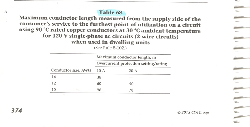
Which may seem silly, until you realize 30 vs 75*C is dictating code:

- Thread starter
- #27
@Waross: I'm not learning in this thread, I don't need to. I already know what I'm doing considering I had something very, very specific in mind. All I asked for was a simple AC resistance value at 30*C. Yet I was met with long posts of why I shouldn't think about 30*C R when a heck of a lot of other people writing and voting on the standards you follow day to day are thinking about it.
With that said I'll come clean and admit I had Table 68 on my mind all along. Perhaps I should have been more clear, but at the same time I see no need to explain every intimate detail of my goals, plans or projects.
With that said I'll come clean and admit I had Table 68 on my mind all along. Perhaps I should have been more clear, but at the same time I see no need to explain every intimate detail of my goals, plans or projects.
Fischstabchen
Electrical
Mbrooke,
Would you design the plumbing in your house to such a degree? No one can eat too much or your 1/2" drain pipe will become fully clogged?
Would you design the plumbing in your house to such a degree? No one can eat too much or your 1/2" drain pipe will become fully clogged?
davidbeach
Electrical
The mark of a good engineer is knowing when “good enough” has been reached. Perfection does not pay the bills no matter how satisfying.
I’ll see your silver lining and raise you two black clouds. - Protection Operations
I’ll see your silver lining and raise you two black clouds. - Protection Operations
- Thread starter
- #30
- Thread starter
- #31
@David: The mark of a good engineer is using his talent and credentials to challenge those laws which are ultimately enforced underneath the barrel of a gun.
Given you unmatched and profoundly respectable understanding of impedance, faults and protective device reach you can destroy the credibility of AFCIs with a single hand. Let alone the rest of NERC, FERC, NFPA-70 and the CEC.
Given you unmatched and profoundly respectable understanding of impedance, faults and protective device reach you can destroy the credibility of AFCIs with a single hand. Let alone the rest of NERC, FERC, NFPA-70 and the CEC.
- Moderator
- #32
Thanks for the information on Table 68.
I'll keep that in mind the next time I have an issue with a ground loop.
(I thought that Table 68 was for the maximum length of a lighting circuit with a distributed load, but what do I know?
I guess that I am the one who should be learning.)
Bill
--------------------
Ohm's law
Not just a good idea;
It's the LAW!
- Thread starter
- #33
@Waross: Going by a 30*C conductor impedance Table 68 guarantees the breaker will trip magnetically (in 1.5 cycles) thus providing parallel arc fault protection.
Here are the calcs but done at 75*C:
So the question then comes up, why does rule 26-724(f) mandate AFCIs when table 68 already provides total parallel arc fault protection coverage?
Series arcing takes place below 5 amps, and is the end result of joule heating (assuming combustion has not already initiated) so series events can not be the prime justification for their mandate.
I encourage you to look at "Restore CSA"
If you think anyone is innocent without bias I'm glad you still have your own innocence.
- Thread starter
- #34
David Beach said:You will never know the source impedance with a sufficient degree of accuracy for any of those to ever matter.
David, respectfully, I will have to strongly disagree with this statement, as much as I normally agree in full with everything you say.
As a primer, I encourage you to Google "Zs=Ze+(R1+R2)" & "Earth Fault Loop Impedance"
The external impedance, though varying, is still mandated into consideration via BS7671, VDE, AS NZS 3000, IEC-60364 and most other electrical codes outside North and Middle America.
Saying these values will never matter is disregarding a standard practice that 90% of the world's population lives under.
Now, disclaimer aside, this is how I view it:
Medium voltage impedance will vary based on switching and even local generation, sure. However, a 150kva padmount and 20 feet of 4/0 AL is unlikely to change over the course of 40 years.
Unless you are dealing with something like a 2,500kva bank, the pole or pad mount transformer(s) along with its service drop is likely to be the overwhelming bulk impedance between every turbine in the Eastern interconnection and the secondary fault point with most typical services.
Whether the 150kva bank serving McDonald's has 12,500 amps of available 13.8kv fault current today by being right next to the 230kv-13.8kv substation or 850 amps tomorrow after a storm takes out the riser 500 feet away and the distribution feeder is now re-fed from another substation 10 miles away there will always be a secondary bandwidth for these two primary values for any given transformer and service drop combination. Always.
Whether the electrician takes his multi function tester readings before or after the storm, or the engineer assumes infinite at the bushing of each 50kva pig, the resulting values are an excellent starting point despite being a rough diamond. In simple terms we know whether we're dealing with an orange or planet Jupiter.
The IEC task force knows these values can change, and as such adds safety factors, modifiers and worse case values (temps, voltage, ect) when calculating disconnection time, perspective fault, and adiabatic limits.
As a result we confidently know the EGC will not fuse, circuits are not likely to trigger ventricular fibrillation during a fault, flicker is within limits, and devices will interrupt fault current without grenading.
I challenge everyone here to plug the numbers for a 15-300kva bank with 50 feet of service drop - one in front of a 60MVA power transformer the other 10 miles out on the line. No matter what, the fault current values at each main disconnect will be relatively similar.
Now add or deduct to the secondary run/drop. Or tweak the bank size. Values will change substantially.
- Moderator
- #35
It is pretty obvious that you do not have a copy of the code that includes Table 68.
Table 68 has nothing to do with fault currents or ground loops.
And as sad as the situation with the CSA may be, what on earth does that controversy have to do with the coefficient of resistance between 30 degrees and 75 degrees?
By the way, given the difference between the DC resistance and the effective AC resistance, does the temperature coefficient of a copper wire apply to the effective AC resistance or to just the DC component of the effective AC resistance.
oops. Back to the spread sheet.
Bill
--------------------
Ohm's law
Not just a good idea;
It's the LAW!
- Thread starter
- #36
And I know critics will raise doubts as to the legitimacy or accuracy of this remark: "fusing of the EGC" "EGC will not fuse" and "adiabatic limits"
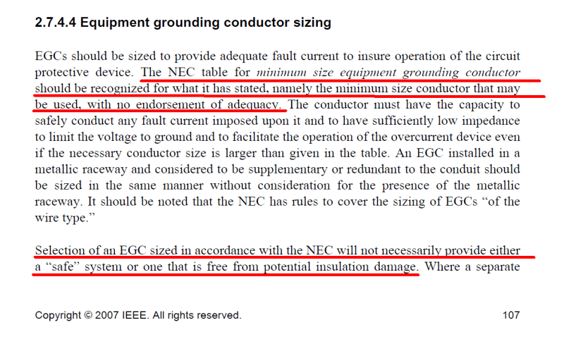
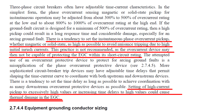
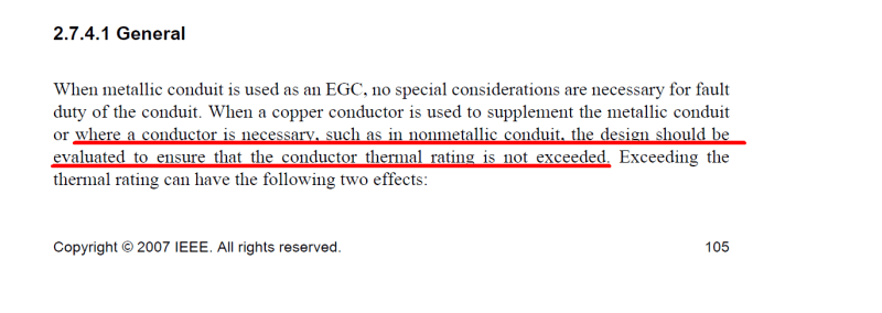
To that I will simply cite the IEEE Green Book which makes numerous references as to Table 250.122 being inadequate when a breaker does not trip magnetically or under exceptionally high fault currents:
Real world pic...
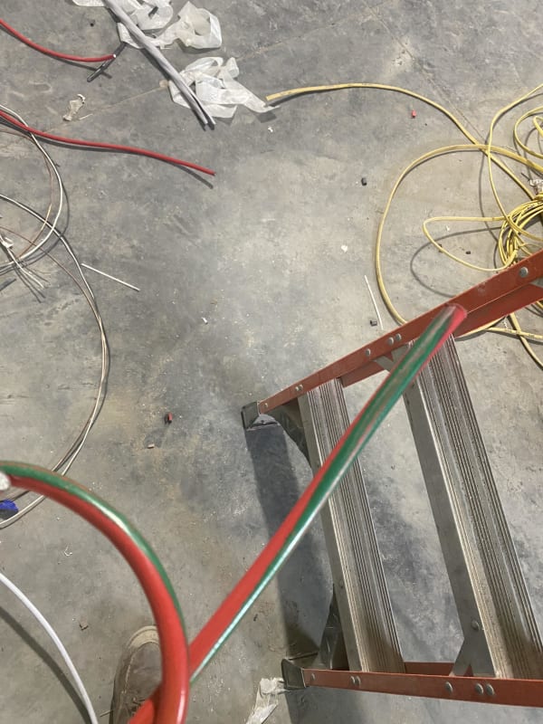
It is for this reason every engineer must compare relative fault current with disconnection times against conductor adiabatic limits.
If this is not done, technically the the EGC must be the same size as the phase conductors for circuits up to 6 AWG, and half size in relation to the mm2 value for circuits over 6 AWG (if not 4AWG).
Ie, a 350 amp circuit without adiabatic consideration, known fault current or disconnection time, would need a 500MCM (253mm2) phase and a 250 MCM (127mm2) equipment grounding conductor.
My reference from IEC 60364-5-54:
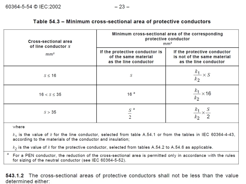
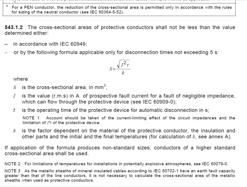
I am very much aware that 99.99% of the time wire EGCs are based on Table 250.122 of the NEC or Table 16 of the CEC without question.
However, if one looks at 90.1 C referencing IEC-60364 or the IEEE it becomes rather apparent that the minimum EGC wire size as listed in NFPA-70 or the CEC may be inadequate under certain conditions.
So I can understand why people would raise eye brows where I have drawing showing what at first notion appears to be grossly oversized equipment grounding conductors- however to that I will say just because it may be technically legal (key word may) does not mean its right, safe or ethical. Or that I am unaware of how to correctly apply the code.
To that I will simply cite the IEEE Green Book which makes numerous references as to Table 250.122 being inadequate when a breaker does not trip magnetically or under exceptionally high fault currents:


Real world pic...

It is for this reason every engineer must compare relative fault current with disconnection times against conductor adiabatic limits.
If this is not done, technically the the EGC must be the same size as the phase conductors for circuits up to 6 AWG, and half size in relation to the mm2 value for circuits over 6 AWG (if not 4AWG).
Ie, a 350 amp circuit without adiabatic consideration, known fault current or disconnection time, would need a 500MCM (253mm2) phase and a 250 MCM (127mm2) equipment grounding conductor.
My reference from IEC 60364-5-54:


I am very much aware that 99.99% of the time wire EGCs are based on Table 250.122 of the NEC or Table 16 of the CEC without question.
However, if one looks at 90.1 C referencing IEC-60364 or the IEEE it becomes rather apparent that the minimum EGC wire size as listed in NFPA-70 or the CEC may be inadequate under certain conditions.
So I can understand why people would raise eye brows where I have drawing showing what at first notion appears to be grossly oversized equipment grounding conductors- however to that I will say just because it may be technically legal (key word may) does not mean its right, safe or ethical. Or that I am unaware of how to correctly apply the code.
- Thread starter
- #37
Waross said:It is pretty obvious that you do not have a copy of the code that includes Table 68.short circuit interrupting.
Do you have a copies of IEC 60364, IEC 61200-413, IEC 60479-1, EPRI guide books, papers written be C.F. Dalziel, research by Frederick F. Franklin, UL C101, UL1699, IEEE working group doc, UL studies presented to CMP2 and others code making panel members?
And as sad as the situation with the CSA may be, what on earth does that controversy have to do with the coefficient of resistance between 30 degrees and 75 degrees?
Same misfeasance and malfeasance which lead to that controversy also lead to the CSA taking bribes mandating AFCIs.
30*C impedance values prove that with the runs restricted to the lengths listed in Table 68 a fault at the furthest point will result in enough current flowing 125% over a modern circuit breakers instantaneous trip threshold which in turn provides complete parallel arc fault protection for the entire circuit.
Table 68 is arc fault protection- effective ground fault current path has been defined and established, yet AFCIs are still mandated despite that which makes no sense.
Of course one will can argue series events, however, arcing is the end stage of joule heating assuming combustion has not already initiated.
In other words a product was put into the code which offer not benefit to life and property. Only gains for those making it.
By the way, given the difference between the DC resistance and the effective AC resistance, does the temperature coefficient of a copper wire apply to the effective AC resistance or to just the DC component of the effective AC resistance.
oops. Back to the spread sheet.
I'd argue just the DC component. But I don't know for sure, which is why I'm asking.
The big players already have the data but are partially tight lipped in hopes of controlling the narrative on their the conclusions aka destination science.
My point the NFPA could define effective ground fault current path instead of mandating AFCIs, GFCIs, GFEPs, SPGFPs, and a slew of other code rules to cover for those 5-10% of cases where a breaker may not trip fast enough.
- Moderator
- #38
If you read the code you would know that Table 68 has to do with maximum allowable voltage drop on residential lighting circuits.
The voltage drop percentages are stated in the code, but table 68 lists maximum circuit lengths despite calculations and only for evenly distributed loading.
Your uninformed hubris is becoming onerous.
I have experienced 15 Amp circuits in conduit that were unable to trip magnetically on a dead short circuit, line to line.
What David Beach said, things change in the real world.
With all your worry about 75C vs 20C vs 30C vs 60c, have you paused to consider that a cooler wire, with less resistance is better able to cause an instantaneous trip.
In 99% of cases, the lower resistance is in your favour.
After dissing my suggestion that interrupting ratings are often conservative, you may consider researching the range of X/R ratios of distribution transformers and look up the assumed X/R ratings that interrupting ratings are based on.
All of your agonizing will be for naught if the transformer has an unusually high X/R ratio.
Interrupting ratings are based on an assumed X/R rating and if an unusual transformer has a higher than assumed X/R ratio, the fault current will be above the calculated interrupting rating.
Conversely, the fault current from a transformer with a lower than assumed X/R rating will be lower than assumed.
Bill
--------------------
Ohm's law
Not just a good idea;
It's the LAW!
FreddyNurk
Electrical
You know that the 30C temperature referenced is the ambient temperature, not the conductor temperature right?
EDMS Australia
EDMS Australia
- Thread starter
- #40
Waross said:If you read the code you would know that Table 68 has to do with maximum allowable voltage drop on residential lighting circuits.
I never said it did.
The voltage drop percentages are stated in the code, but table 68 lists maximum circuit lengths despite calculations and only for evenly distributed loading.
Which would be a general use or typical residential circuit.
Your uninformed hubris is becoming onerous.
Do the math like I have, and the research. It becomes obvious what Table 68 is really trying to achieve.
I have experienced 15 Amp circuits in conduit that were unable to trip magnetically on a dead short circuit, line to line.
Of course! Circuit length plays a role, as well as older breaker some of which did not even have magnetic trip. Those that did often were just starting around 20-25x. Even modern 2 and 3 pole breakers tend to be higher than 15 and 20 amp single pole breakers and that is intentional.
What David Beach said, things change in the real world.
With all your worry about 75C vs 20C vs 30C vs 60c, have you paused to consider that a cooler wire, with less resistance is better able to cause an instantaneous trip.
You're preaching to the choir. Of course! And that is exactly what I wanted to validate.
In 99% of cases, the lower resistance is in your favour.
After dissing my suggestion that interrupting ratings are often conservative, you may consider researching the range of X/R ratios of distribution transformers and look up the assumed X/R ratings that interrupting ratings are based on.
All of your agonizing will be for naught if the transformer has an unusually high X/R ratio.
Interrupting ratings are based on an assumed X/R rating and if an unusual transformer has a higher than assumed X/R ratio, the fault current will be above the calculated interrupting rating.
Conversely, the fault current from a transformer with a lower than assumed X/R rating will be lower than assumed.
Breakers are tested with really extreme X/R ratios. However, I do not and will not assume. I want numbers, and will do the math. I like it that way
- Status
- Not open for further replies.
Similar threads
- Replies
- 8
- Views
- 891
- Question
- Replies
- 1
- Views
- 2K
- Locked
- Question
- Replies
- 0
- Views
- 2K
- Question
- Replies
- 12
- Views
- 18K
- Locked
- Question
- Replies
- 8
- Views
- 6K
