Navigation
Install the app
How to install the app on iOS
Follow along with the video below to see how to install our site as a web app on your home screen.
Note: This feature may not be available in some browsers.
More options
Style variation
-
Congratulations cowski on being selected by the Eng-Tips community for having the most helpful posts in the forums last week. Way to Go!
You are using an out of date browser. It may not display this or other websites correctly.
You should upgrade or use an alternative browser.
You should upgrade or use an alternative browser.
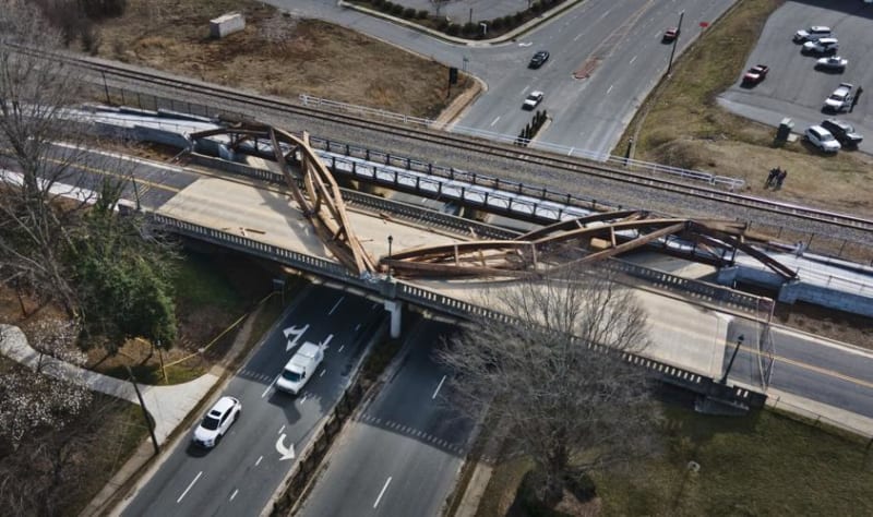
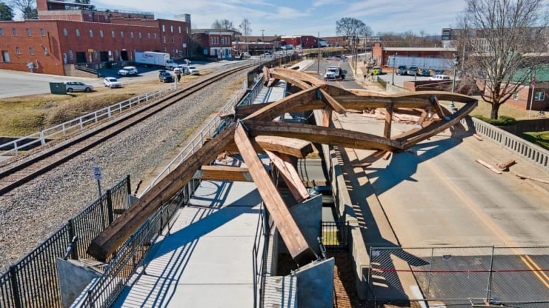
40-ton timber arches collapse in Hickory, NC 35
- Thread starter bugbus
- Start date
- Status
- Not open for further replies.
LittleInch
Petroleum
There seems to be an awful lot of concentration of bending moment at those mechanical flanges alright. Were the two of them tied together at the top? It looks like it to me from a bit of googling.
Maybe those wires are like the ones on the FIU bridge and there to prevent the bridge from bouncing too much?
Google street view hasn't updated with it built unfortunately but there are plenty of pictures out there.
Remember - More details = better answers
Also: If you get a response it's polite to respond to it.
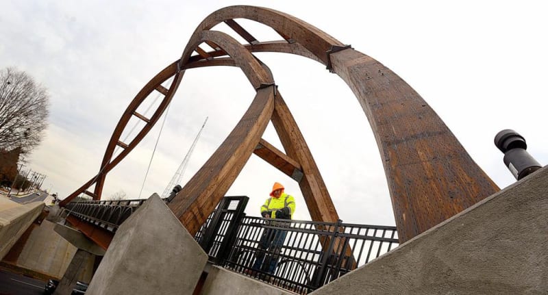
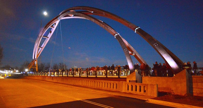
When function follows form, instead of the other way around, you end up with a bridge like this;
Link
It's not apparent from most of the pictures, but this is a single inclined arch
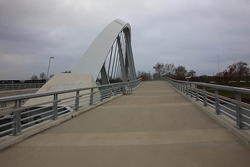
Opening was delayed for some time until everyone was sure it wouldn't collapse.
Brad Waybright
The more you know, the more you know you don't know.
Link
It's not apparent from most of the pictures, but this is a single inclined arch

Opening was delayed for some time until everyone was sure it wouldn't collapse.
Brad Waybright
The more you know, the more you know you don't know.
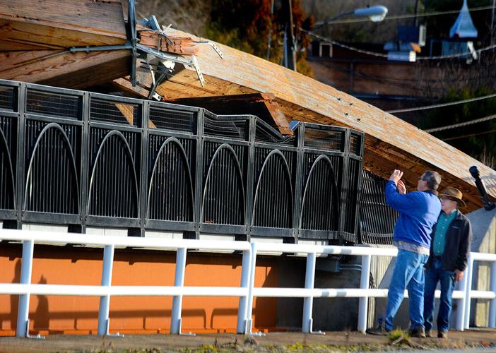
The hinge connections looked pretty flimsy to me; structure with a certain level of stiffness based on its footprint narrows down to less than 1/10th its base width, supplemented by at most 1" of steel and screws that appear to have pulled out pretty easily
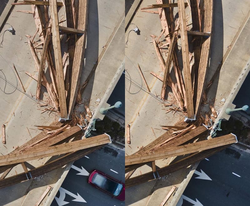
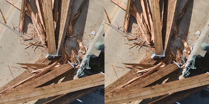
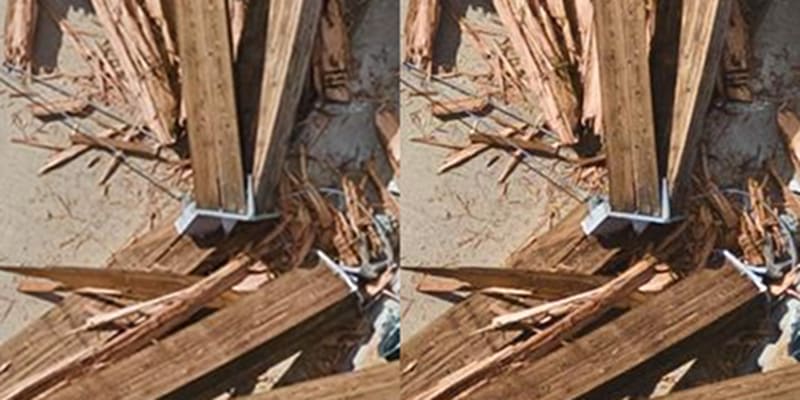
The base connections in the image above also appear to have been flimsy; whatever screws they used to secure the wood to the metal plates simply pulled straight out, while the hinge connection screws simply splintered their way through the wood.
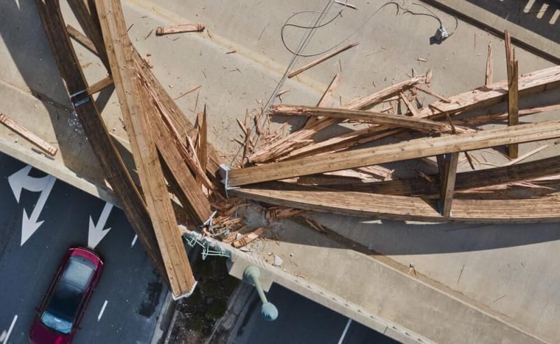
This is a pretty good picture
TTFN (ta ta for now)
I can do absolutely anything. I'm an expert! faq731-376 forum1529 Entire Forum list
The base connections in the image above also appear to have been flimsy; whatever screws they used to secure the wood to the metal plates simply pulled straight out, while the hinge connection screws simply splintered their way through the wood.
This is a pretty good picture

TTFN (ta ta for now)
I can do absolutely anything. I'm an expert! faq731-376 forum1529 Entire Forum list
I suspect gusmurr identified the real cause of the failure.
I agree that it looks frighteningly unstable at first glance, but most of that is resolved by internal bracing. I think the interplay of the two arches confuses the shape - some of the 'straight-through' shots make it look symmetrical. The global shape appears to be roughly parabolic, and 3 pinned arches are relatively common. So no moment is transferred from one half to the other at the middle connector by design.
Regarding fasteners in the connector plates, I wouldn't go so far as to say they "pulled through easily" - perhaps they did, but perhaps that was because the joint experienced 10x its design stress due to a failure elsewhere in the structure.
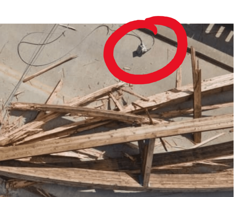
Check this from the picture IRstuff posted. This looks suspiciously like a terminal connection of a cable to the concrete pier. I would not expect this to be a secondary failure - if the arch itself had failed a wind of only 30mph our so would not be sufficient to blow it out and maintain significant tension as it went down. It likely would have crumpled and come down, leaving those connections in tact.
My theory: the incredibly inefficient cable brace angle led to excessive tension in the cable, and it precipitated a failure in the cable connection. (I wonder if there was a request to use adhesive anchors for the cable terminals...) When that came out, the arch lost all lateral stability, which then caused the joints to experience out of plane moments for which they were not designed.

-
1
- #26
When that came out, the arch lost all lateral stability
That would seem to argue that the cable brace was woefully inadequate, given that it was a single-point failure mechanism.
but perhaps that was because the joint experienced 10x its design stress due to a failure elsewhere in the structure.
Given that the cable was a single-point failure, the joints should have been designed to handle the loads that would arise from that failure, one would think.
TTFN (ta ta for now)
I can do absolutely anything. I'm an expert! faq731-376 forum1529 Entire Forum list
-
1
- #27
IRstuff said:That would seem to argue that the cable brace was woefully inadequate, given that it was a single-point failure mechanism.
That it would. I never said it was a good design.
IRstuff said:Given that the cable was a single-point failure, the joints should have been designed to handle the loads that would arise from that failure, one would think.
If that were the case, it wouldn't be a single point failure. And if this were an integral part of the bridge and not decorative, you'd probably be right. But as the failure of the arch had nothing whatsoever to do with the stability of the bridge itself, I'm guessing it didn't undergo the same kind of scrutiny with respect to design adequacy and redundancy.
I'm not sure what the cables are for... if to provide support of something below, they might have been OK. If to provide lateral support at the top, not so good. Any horizontal load at the top would greatly increase the force in the cable because of the 'steep slope'. We'll have to wait and see why it 'broke'. ![[ponder] [ponder] [ponder]](/data/assets/smilies/ponder.gif)
Rather than think climate change and the corona virus as science, think of it as the wrath of God. Feel any better?
-Dik
![[ponder] [ponder] [ponder]](/data/assets/smilies/ponder.gif)
Rather than think climate change and the corona virus as science, think of it as the wrath of God. Feel any better?
-Dik
The connectors require more info:
1. Is the connector from the top of the arch or from the pier crosshead?
2. The cable appears cut close to the loose connector. Is that from tension prior to collapse or from being restrained/sheared from the momentum of the collapse? The loose ends do not appear to be frayed, at least not significantly.
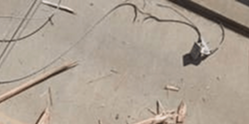
-
1
- #31
Alistair_Heaton
Mechanical
Could the cables be for keeping the whole thing in compression all the time?
The two cables had to be in tension, if nothing else, so they didn't look all loose and flappy and stupid.
How much tension?
If one side failed, then the horizontal vector up top for the other cable would surely add lateral force up there.
Would that be a bad thing?
spsalso
How much tension?
If one side failed, then the horizontal vector up top for the other cable would surely add lateral force up there.
Would that be a bad thing?
spsalso
Alistair_Heaton
Mechanical
Some buff body dynamic action and the wires are to stop vibrating?
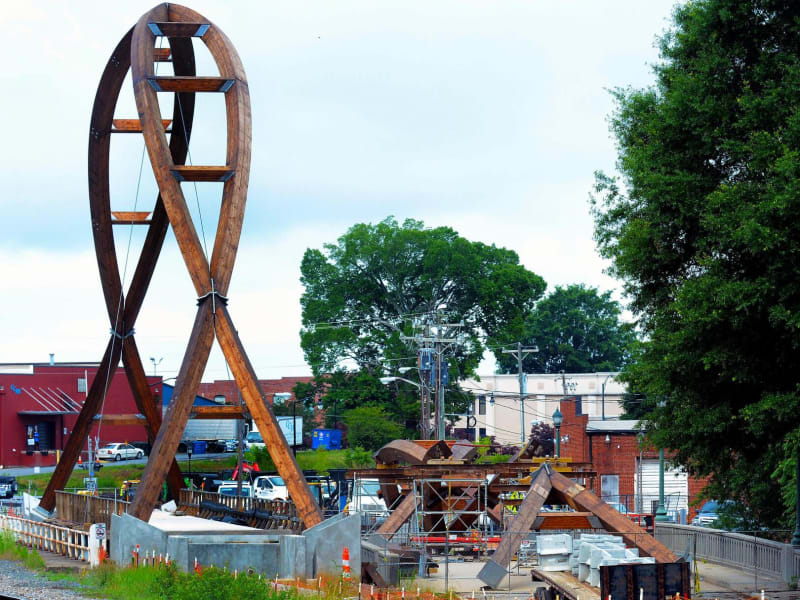
As of Mar 23, 2021, prior to the installation of the second arch:
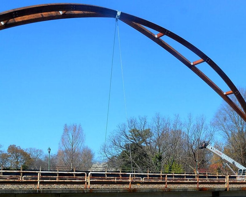
(hickoryrecord.com)
The top connector resembles the loose connector found on the bridge deck after collapse:
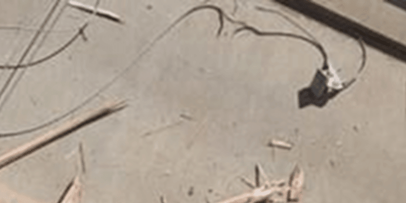
In December 2021, after the installation of the second arch, it appears that a second cable is connected to the upper bracket, to the outside of the initial cables.
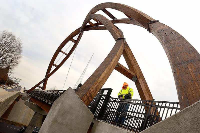
(newsadvance.com)
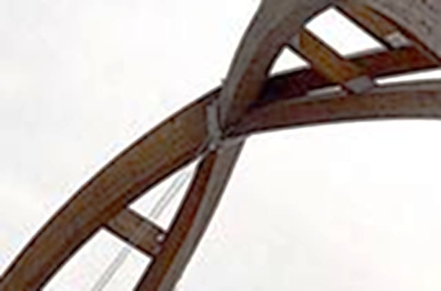
(newsadvance.com)
The lower connector is distinctly different from the loose connector on the bridge deck.
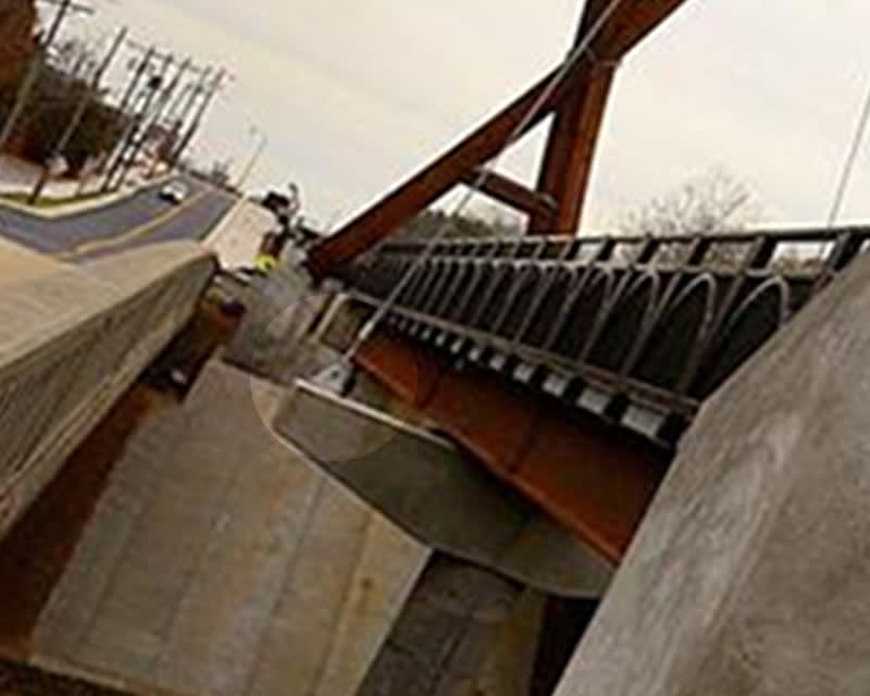
(newsadvance.com)

(hickoryrecord.com)
The top connector resembles the loose connector found on the bridge deck after collapse:

In December 2021, after the installation of the second arch, it appears that a second cable is connected to the upper bracket, to the outside of the initial cables.

(newsadvance.com)

(newsadvance.com)
The lower connector is distinctly different from the loose connector on the bridge deck.

(newsadvance.com)
Sorry 'bout that. I was just trying to get a better understanding of the connectors. It's seems odd that the cable snapped near the upper connector while at the same time the connector broke free of the larger weldment. There's more to learn.
Upper connector, enlarged from previous image:
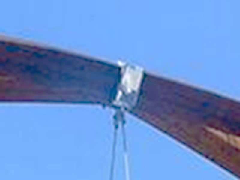
(hickoryrecord.com)
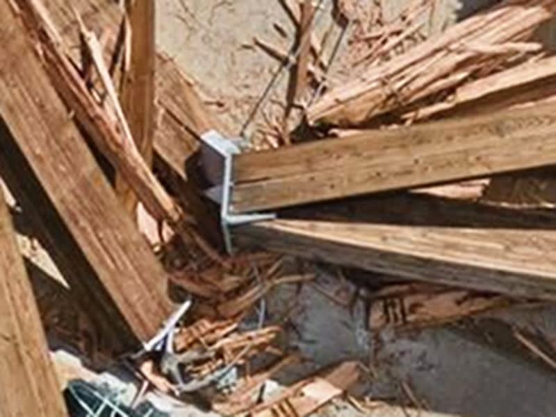
Upper connector, enlarged from previous image:

(hickoryrecord.com)

-
1
- #38
MintJulep said:I think the cables were there to pretend to hold up the bridge.
Not to pretend to stabilize the arch.
I think you got it. The cables might have helped stabilise it, but they're essentially decorative. Decorative cables on a decorative arch.
In any case, those cables could be tensioned up fairly tight, like guitar strings. You're not tensioning a gravity load, you're tensioning between hard points (the headstock, and the arch).
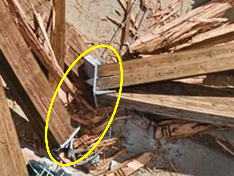
That particular picture is really bothersome. My impression of the connections is that end plates were screwed onto the ends of the beams and the plates were bolted together at the connections, such as the hinge point, but that picture is showing plates but no protruding screws/bolts. Either the bolted-together plates are still intact, then there should be lag screws, or whatever, protruding from the exposed side of plates, or, the plates separated, which would seem to require some plastic deformation as each bolt broke, but the plates look kind of pristine
TTFN (ta ta for now)
I can do absolutely anything. I'm an expert! faq731-376 forum1529 Entire Forum list

TTFN (ta ta for now)
I can do absolutely anything. I'm an expert! faq731-376 forum1529 Entire Forum list
- Status
- Not open for further replies.
Similar threads
- Replies
- 35
- Views
- 13K
- Replies
- 13
- Views
- 13K
- Replies
- 8
- Views
- 6K
- Replies
- 1
- Views
- 648
- Replies
- 46
- Views
- 6K

