Navigation
Install the app
How to install the app on iOS
Follow along with the video below to see how to install our site as a web app on your home screen.
Note: This feature may not be available in some browsers.
More options
Style variation
-
Congratulations TugboatEng on being selected by the Eng-Tips community for having the most helpful posts in the forums last week. Way to Go!
You are using an out of date browser. It may not display this or other websites correctly.
You should upgrade or use an alternative browser.
You should upgrade or use an alternative browser.
40-ton timber arches collapse in Hickory, NC 35
- Thread starter bugbus
- Start date
- Status
- Not open for further replies.
dik,
I never saw any shop drawings of those pipes. Granted, the design drawings did show them with end plate connections to the top deck, but I always assumed there would be slip connections of some sort when they got around to installing them.
I never saw any shop drawings of those pipes. Granted, the design drawings did show them with end plate connections to the top deck, but I always assumed there would be slip connections of some sort when they got around to installing them.
-
1
- #62
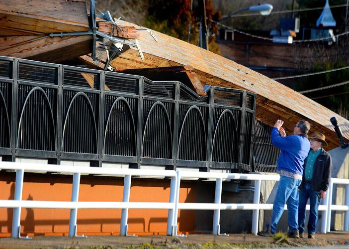
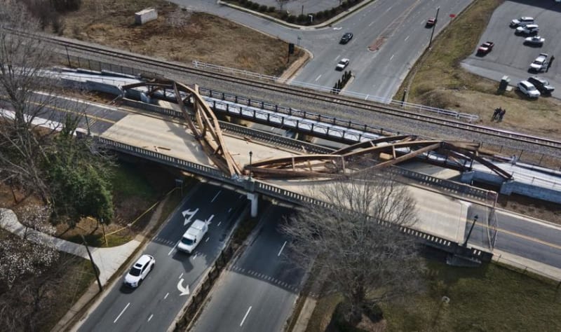
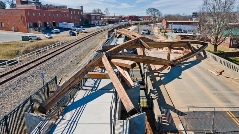
The wishbone connections on the lower arch appear to have suffered worse damage than those on the upper arch. The south east leg of the lower arch even ended up beneath the bridge. Also notable is that the center of the arch pushed slightly east, in keeping with the wind direction relative to the span.
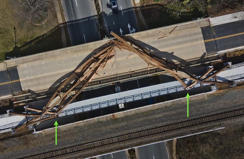
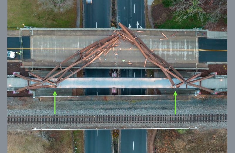
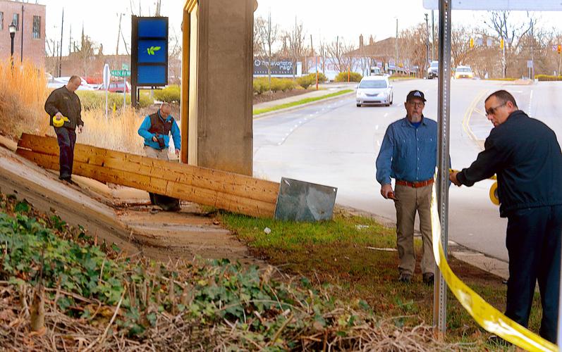
It's hard to say exactly how it all went down (so to speak) but I don't think any of the engineering imagined the degree of freedom represented in the following gif, which is what I tried to explain earlier in this thread.
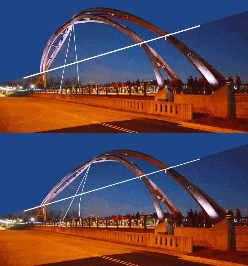


It's hard to say exactly how it all went down (so to speak) but I don't think any of the engineering imagined the degree of freedom represented in the following gif, which is what I tried to explain earlier in this thread.

Alistair_Heaton
Mechanical
dik the lack any real beef to them is the reason why I think it might be dynamic response.
As for the wind loading being ok initially with one span and then fail with two.
I am thinking biplane.

Lift off the spans would put even more load on the wires.
As for the wind loading being ok initially with one span and then fail with two.
I am thinking biplane.

Lift off the spans would put even more load on the wires.
TugboatEng
Marine/Ocean

This picture was posted earlier. These perforated metal strips must have been the repair as they're not visible in other images.
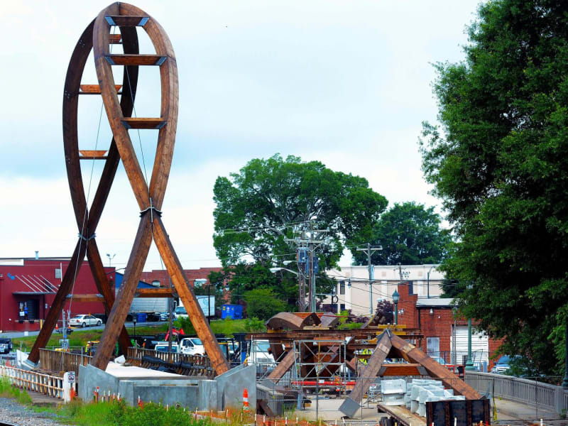
The arches seem to be flanged together in th lower 1/3. I question the strength of the flanges that connect the arches at 1/3rd height. They are so very thin. It's so bad it's as of someone forgot to carry a zero.
-
1
- #65
LittleInch
Petroleum
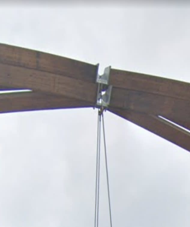
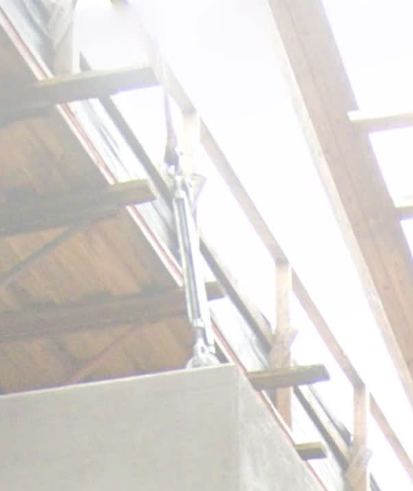
Actually it turns out the north bound carriageway of the road underneath the bridge has street view photos from Sep 21.
Make of these what you will. I don't understand them but that centre connection looks like a pin to me. Also the turnbuckles on the wires are nearly out of room on tension.
Remember - More details = better answers
Also: If you get a response it's polite to respond to it.
Make of these what you will. I don't understand them but that centre connection looks like a pin to me. Also the turnbuckles on the wires are nearly out of room on tension.


Remember - More details = better answers
Also: If you get a response it's polite to respond to it.
SWComposites
Aerospace
Obviously designed by an artist and not an engineer. That pin joint at the top would have been rejected in 15 seconds by any half competent stress analyst. The other “connections” look horrible also.
The gif is neat, but did anyone notice that degree of motion? The cable would hang and not flex and would 'snap back' when movement went the other direction. If the movement were an inch or two rather than what appears to be a couple of feet, hopefully someone would have run up a red flag. The wind speed was low (like 35mph), but the kicker would be the gustiness of it. Does anyone know? Maybe set up harmonics, or overload... like 35mph gusting to 70mph?
Alistair: you notice that the cable bracings are at a 'shallow angle' If they were at a steep angle, the tension load induced in the strand would be huge with any lateral loading on the and they would likely tear free from whatever they were attached to.
Rather than think climate change and the corona virus as science, think of it as the wrath of God. Feel any better?
-Dik
Does anyone know if an engineer was involved? Western Wood Structures is a fairly reputable supplier and I suspect the connections would have been designed by them or at least checked...
It appears the wind speeds were in km/hour, and not mph on my last post.
Rather than think climate change and the corona virus as science, think of it as the wrath of God. Feel any better?
-Dik
Dunno... the top hinge is fairly tall for the span and the reaction at the crown pin in horizontal shear, if half arch is 20T, would be approx 40x0.5x0.5 about 10K plus whatever wind loads are applied (they could be big)... these are not a real big loads, so the connection may be adequate. Looking at the framing, 80K seems like a pretty big weight for the timbers, but I haven't tried to see what the real load is.
Rather than think climate change and the corona virus as science, think of it as the wrath of God. Feel any better?
-Dik
Alistair_Heaton
Mechanical
dik said:Alistair: you notice that the cable bracings are at a 'shallow angle' If they were at a steep angle, the tension load induced in the strand would be huge with any lateral loading on the and they would likely tear free from whatever they were attached to.
Yes I did and there was no load fuse.
Thats why I think they were only envisioned to alter the natural frequency but only in one plane.
LittleInch
Petroleum
I also wonder if the top arch was really designed to sit or rest on the bottom one? Maybe it's all shrunk a little or bent a bit more and the two were supposed to be separate? Or the tension in the wires was not as it should have been and the top set were forced more onto the bottom set of beams?
Remember - More details = better answers
Also: If you get a response it's polite to respond to it.
Remember - More details = better answers
Also: If you get a response it's polite to respond to it.
Alistair_Heaton
Mechanical
yes, the one I saw with a similar purpose, shear pin but then it had a secondary load path came into action which had a sprung damping element to it.
When I say saw, it was a FEA model. The attachment to the support was many times stronger than the tensioning wire. It was a controlled failure analysis if that makes sense. The dynamic engineer took it off me once I had created the input deck for nonlinear geom, it was as well a piece of "Art" and I don't have a clue if it was ever made.
It was a welder that apparently triggered a more in depth look at the dynamics of it.
-
3
- #75
MJCronin said:Why is no one discussing responsibility here ?????
1) We're more interested in why it happened - we're engineers, not lawyers.
2) Until you know why it happened, it's difficult to determine who is responsible. Was it an inherently flawed design? Was there an error in the shop and the 1-1/2" plate callout on the drawings was recopied onto the shops as 1/2"? Was the epoxy adhesive applied correctly? Each of those has a different person who is "responsible" for the error. The EOR is involved at each of those stages, but we're not going to burn him/her at the stake until we know that it was his/her mistake that was the root cause.
-
1
- #77
LittleInch
Petroleum
Well the first thing everyone did was promptly pass on responsibility to the people making it....
I strongly suspect Western Wood Services provided the design, manufacture and installation.
Remember - More details = better answers
Also: If you get a response it's polite to respond to it.
I strongly suspect Western Wood Services provided the design, manufacture and installation.
Remember - More details = better answers
Also: If you get a response it's polite to respond to it.
One way that it would help to figure out WHY it happened is to have the drawings for the project. If there were any changes between start and finish, those could be informative, also.
I expect those should come out in the near future. Unless, of course, there's a reason not to "share".
spsalso
I expect those should come out in the near future. Unless, of course, there's a reason not to "share".
spsalso
I strongly suspect Western Wood Services provided the design, manufacture and installation.
I think the articles say that the sub did the installation, with some support from Western Wood
TTFN (ta ta for now)
I can do absolutely anything. I'm an expert! faq731-376 forum1529 Entire Forum list
- Status
- Not open for further replies.
Similar threads
- Replies
- 35
- Views
- 13K
- Replies
- 13
- Views
- 13K
- Replies
- 8
- Views
- 6K
- Replies
- 1
- Views
- 664
- Replies
- 48
- Views
- 14K

![[pipe] [pipe] [pipe]](/data/assets/smilies/pipe.gif)