Continue to Site

Eng-Tips is the largest engineering community on the Internet

Intelligent Work Forums for Engineering Professionals

  • Congratulations KootK on being selected by the Eng-Tips community for having the most helpful posts in the forums last week. Way to Go!

A funny statics problem 13

Status
Not open for further replies.

NedGan76

Structural
Apr 4, 2022
36
Hi, everyone!

Here is an interesting and funny statics problem, to exercise engineering brains and cheer up.

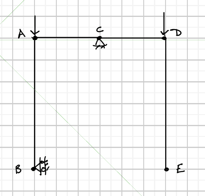
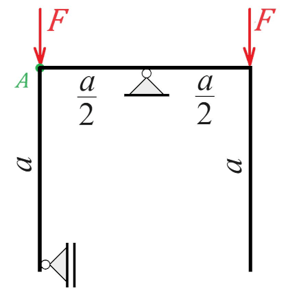
Given the following structure can you tell, without calculating, in which direction point A will move after deformation:
A) up
B) down
C) will not move

... and why? Point A is not a hinge. No structural analysis programs allowed. 😜
Problem_g0lfgd.png
 
Replies continue below

Recommended for you

I really need to stay off this site over the weekend. This problem is making me question if I know anything.

I think Kootk’s analysis is mostly correct. I went through the same statics exercise and got zero horizontal reaction at the bottom left support. It seems like there should be a force though.

I think it would be possible for point A to move down if the left vertical had zero stiffness and weighed more than the right vertical. The problem says nothing about the segments all being uniform, so I’ll assume this is legal.

If the segments all need to be uniform, then I would say that the left end of the horizontal segment (point A) would have to be higher than the right end because the left end has some resistance to deflecting downward but the right does not. But if the right end is lower than the left, that doesn’t necessarily mean that point A goes up.
 
I would say there is a horizontal reaction at the roller below A.

Let's assign points A, B, C, D going clockwise around the figure, so we have A as noted, center support is B, point with applied force on the right is C, and the roller at the bottom is D. X is the horizontal axis, Y is the vertical axis.

Eq 1: ΣM[sub]A[/sub]=R[sub]Dx[/sub]*a+F*a/2-R[sub]By[/sub]*a/2=0 => R[sub]By[/sub]=F+2R[sub]Dx[/sub]

Eq 2: ΣF[sub]x[/sub]=R[sub]Dx[/sub]+R[sub]Bx[/sub]=0 => R[sub]Dx[/sub]=-R[sub]Bx[/sub]

Eq 3: ΣF[sub]y[/sub]=F+F-R[sub]By[/sub]=0 => 2F=R[sub]By[/sub]

Substitute the result of Eq 3 into result from Eq 1:

2F=F+2R[sub]Dx[/sub] => R[sub]Dx[/sub]=F/2 (Horizontal Reaction at roller is F/2


like Koot I believe this to be independent of member stiffness, he articulated it much better than I likely am about to:

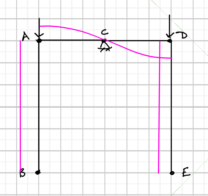
Screenshot_2023-10-14_141125_jtxqtf.png


Lets assume the restraint at B is removed, then the deformed shape and rotation would be:
Deformation:
Screenshot_2023-10-14_141705_mft7ow.png

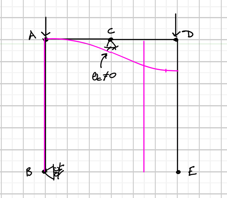
Rotation:
Screenshot_2023-10-14_141719_arxtpk.png


Note that because there is no loading on the vertical legs and the joints are rigid that their cross-section rotations must be constant and match that of the horizontal member ends,
ΘAB = ΘAC
ΘDE = ΘDC
These are compatibility requirements as KootK noted for the rotations to be different work must be done in member AB or member DE, because there is no load on these members there is no work so this is independent of the section properties.

Now restoring the restraint, then because there is no loading on member AB it's cross-section rotation must become 0 and by compatibility so must the rotation at A:
Screenshot_2023-10-14_142601_hswzxo.png

This has shifted the AC-CD rotation diagram downward by ΘAC of the unrestrained case, which makes the rotation at C go from 0 to -ΘAC. Sign convention on Θ is counterclockwise positive so a negative rotation is clockwise indicating that the slope of the deflection curve coming from A to C is negative which indicates that A is above C since C is restrained.

A does not move to the right because there is no shear in member AB therefore there is no axial force in member AC so no axial deformation can occur and because of the restraint at C the "pulling" action of CD-DE is absorbed by members at the support as bending.
 
I didn't realize the bottom left is released for vertical movement. That changes it somewhat, but I still think the bending of the top horizontal will produce a moment at point A and a horizontal reaction at the lower left support (balanced by a horizontal reaction at the top center support).

The top bends down on both sides, producing rotation at Point A, which bends the left side vertical in.

I still maintain that Point A will move to the right from the curve in the top member and shortening due to axial compression in the top.

However, because the left side of the top member is restrained against rotation, and the right side is not, the left will move down more than the left. If there's no limit on how far the left side can slide up, I think the unbalanced moment due to the horizontal reaction at the bottom support, will cause the top member to continue to rotate. So, without additional boundary restraints, the system is unstable. I think this is what FEA way's model shows.
 
Celt - I agree with nearly everything except the lack of axial force in A-C (and follow on tweaks to the presence of moments and shears). If there is no horizontal reaction at your point B, then there would be no difference between the deflected shape in your first diagram vs. the final deflected shape. If there is a horizontal reaction at your point B, then there must be an equal and opposite horizontal reaction at point C, which means there must be axial force in A-C.
 
pham:
I believe:
"Eq 1: ΣMA=RDx*a+F*a/2-RBy*a/2=0 => RBy=F+2RDx"
should read
Eq 1: ΣMA=RDx*a+F*a-RBy*a/2=0 => RDx = 0, noting that RBy = 2*F
total length from F at the right joint to joint A is 2*(a/2) = a

Under this specific configuration there is no horizontal reaction.
 
hmmm...I suppose you are correct...

But that leaves the question: why are the deflected shapes different if there is no reaction? If there is no reaction, we should be able to remove the boundary condition and not have it effect the final result. I realize it would leave it 'technically' unstable, but with balanced forces there would be no theoretical rotation anyway.

If the restraint causes the deflected shape to change, there must be a reaction there.
 
phamENG said:
But that leaves the question: why are the deflected shapes different if there is no reaction?

I agree, and that's part of what makes this so interesting. I would answer your question this way:

1) Our conventional analysis techniques seek out only the configuration that is in energetic harmony at the end of the structure's load/deformation journey. They gloss over time history.

2) To get to the deflected shape that the structure finally assumes, there must have been points in time during the load history where, indeed, there was a horizontal reaction.

3) The horizontal reaction strained the left post and the left post relieved itself of that by rotating the entire frame clockwise.

I know, it kind of has one craving the blue pill.
 
Kootk said:
Our conventional analysis techniques seek out only the configuration that is in energetic harmony at the end of the structure's load/deformation journey. They gloss over time history.

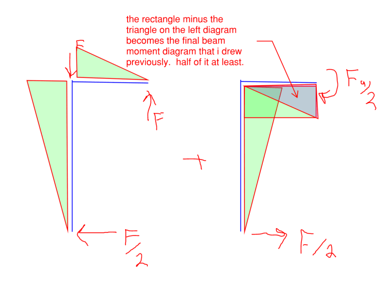
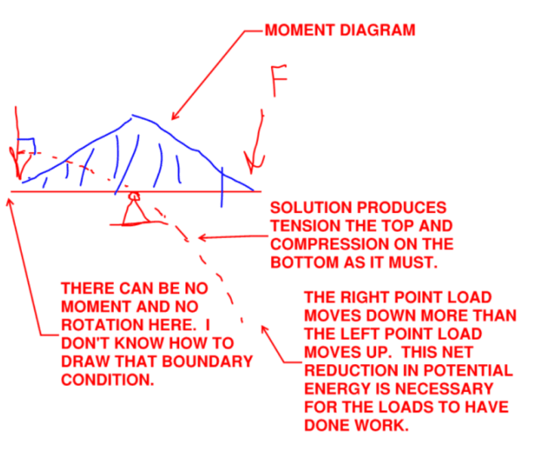
Try it this way pham:

1) Study just the left half of the frame. The rest is extraneous.

2) Use superposition not just as a tool but as a literal expression of loads being added over a finite time span. First the load on the left, then the load on the right.

As you can see, when the two moment diagrams are added together, you get:

a) No horizontal reaction.

b) No Moment at A.

c) No moment anywhere in the left post, and therefore no curvature.

d) The final, triangular moment in the beam that I proposed earlier. Or, at the least, a mirror of it. For some reason I switched from tension side to compression side moment diagrams.

I've repeated the previous sketch below as I imagine that it will be easier for folks to view them together for comparison.

C01_l8iwn8.png


C01_ivmq2c.png
 
I think this structure is unstable when considering linear analysis (elastic material, small displacements, infinitesimal strain theory). It is free to rotate about the top central pin support.

KootK said:
To get to the deflected shape that the structure finally assumes, there must have been points in time during the load history where, indeed, there was a horizontal reaction.

Because it is unstable, the magnitude of this horizontal reaction is infinitesimally small.
 
After reading the above comments I agree it moves upwards.

The diagonal dimension AB is slightly shorter in the deflected case, meaning the roller moves up slightly to make up the difference.
 
1) Our conventional analysis techniques seek out only the configuration that is in energetic harmony at the end of the structure's load/deformation journey. They gloss over time history.

2) To get to the deflected shape that the structure finally assumes, there must have been points in time during the load history where, indeed, there was a horizontal reaction.

3) The horizontal reaction strained the left post and the left post relieved itself of that by rotating the entire frame clockwise.

I think you've got it there. Kootk. It will look like the second diagram Celt83 posted, just rotated clockwise so the the left bottom is in it's original position horizontally, because, of course, it never actually moved.

That puts Point A up and slightly to the right of its original position.

Assuming weightless members, it reaches equilibrium with zero horizontal force in the bottom support. If the members have weight, there will be horizontal forces at the supports, because the CG of the frame is no longer aligned with the top support (the CG of the right leg moves left more than the CG of the left leg moves to the right).
 
From a virtual work standpoint:
Virtual Force 1k Up at A
Member AB has no virtual work because the real/virtual axial force = 0 and the real moment = 0

Member AC:
Real M = -F*x
Virtual M = x-a/2

∫ M*Mv / EI dx, from 0 -> a/2 = F a^3 / 48 EI

Real Axial = 0 so no axial component of work

Member CD has no virtual work because it has no real/virtual axial force and the virtual moment = 0

Member DE has no virtual work because the real/virtual axial and moment are 0

Virtual force 1k to the right at A
All Virtual Components except axial in AC are 0 and Real Axial in AC is 0 so no virtual work is done and there is no deformation to the right

Total deflection at A:
F a^3 / 48 E I, upward and E and I are for beam segment AC only so independent of other member stiffness
 
I haven’t had time to read all the posts but I do have a couple of observations. When loaded, the horizontal member is fixed horizontally and free to rotate. The thing is, the LHS of the horizontal beam will shorten (due to bending) w.r.t the fixed point, be it if it moves up or down, thereby displacing the top end of the LHS vertical member, and thus causing a reaction at the bottom restraint. In addition, any reaction at that restraint will generate a moment in the top LHS, due to the member being in tension, the equation being a 2nd order differential.
 
This turns out to be quite a simple problem, after one has banged one's head against the brick wall for long enough.[ ] Start by ignoring the vertical beam and the horizontally acting roller support entirely.[ ] Then our beam is like a see-saw with equal downwards loads at each end, and it will be hogging along its entire length (except for the very end points that will not be experiencing any moment).[ ] At the left hand end the deflection is d (downward deflection positive) and the rotation is r (upwards slope positive).[ ] At the midpoint deflection and rotation are zero.[ ] At the right hand end deflection is d and rotation is -r.[ ] However, like with a see-saw, the system is not fully constrained and can rotate freely about the centre point.

Now consider what happens when we incorporate the downwards leg to the roller support.[ ] This constrains the see-saw motion.[ ] As many contributors above have pointed out, overall horizontal equilibrium requires that the force imposed by the roller support is zero.[ ] So the downwards leg will experience no internal forces and will remain perfectly straight.[ ] It also has to be vertical, and to accommodate this requirement the entire see-saw has to rotate clockwise through an angle equal to r.[ ] Under small displacement theory this means that point A will now move upwards by an distance equal to 2d, so it is now at a location a distance d ABOVE its initial unloaded location.


[sub][ ]—————————————————————————————————[/sub]
[sup]Engineering mathematician / analyst.[ ] See my profile for more details.
[/sup]

 
Point A will move up, since structure is restraint on Left side while the right side is free to rotate
Assuming both side of structure are identical in geometrical/stiffness rigidity
..
the problem is like simple two balance weight but with small spring on the left side (this sring will cause some delay of displacement)
I Think [pipe]
 
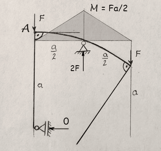
This problem is interesting and funny because the solution is the opposite to what our intuition says. And here is the solution:

First, find the support reactions:
For the vertical support in the middle - from ∑V = 0 => V_t = 2F
For the horizontal support at bottom left support - from ∑M = 0 (around the top support) =>
∑M = H_b*a + F*a/2 - F*a/2 = 0 => H_b = 0
For the horizontal support at top middle support - ∑H = 0 => H_t = H_b = 0.

The bending moment diagram in the beam is triangular with a peak above the support M = F*a/2.
The bending moment in the columns is M = 0.

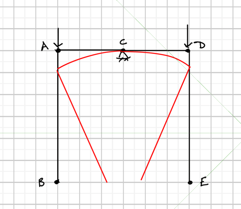
From now on, the solution may come directly from the properties of the deflection curve (see the picture bellow):
1. Since there are no bending moments in the left column, it remains straight.
2. It also remains vertical because the bottom sliding support does not allow it to rotate freely as the right one.
3. The right angle at the corner should remain right after the deformation.
4. The bending moment in the beam is on top, so the curve is bulged upwards. Since the leftmost tangent is horizontal (to preserve the right angle), point A has nowhere to go, but above the middle support. 🙂

problem_qiaieq.png


Cheers!
Ned Ganchovski

A better software for your calculation notes, free and open source:

 
Capture_sjh7vu.jpg


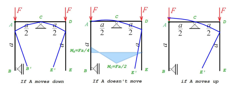
If column weights are neglected, then:
[ul]
[li]If A moves down, B would need to move to B', which is prevented by the roller support at B.[/li]
[/ul]
[ul]
[li]If A stays where it is, the sum of moments on Beam AC requires a reaction at A greater than F, so it must move up.[/li]
[/ul]
[ul]
[li]If A moves up, rotation at A is zero. The c.g. of column DE has moved toward C, but column weight has been neglected.[/li]
[/ul][pre][/pre]
 
"But that leaves the question: why are the deflected shapes different if there is no reaction? If there is no reaction, we should be able to remove the boundary condition and not have it effect the final result. I realize it would leave it 'technically' unstable, but with balanced forces there would be no theoretical rotation anyway.

If the restraint causes the deflected shape to change, there must be a reaction there." --Phameng

Long discussion, don't know if this is answered already. It's in neutral equilibrium without the roller support. The seesaw part could rotate to any angle and stay there. The roller support sets the rotation angle and would provide a reaction if the seesaw tries to deviate but otherwise zero reaction. Like the tension stabilisers of a tensegrity table.
 
Yea, that is the MF for me. If there is no reaction in the left column, how is it affecting the deflected shape?
I ran it on my FEA for giggles and it does confirm the answer.
 
Status
Not open for further replies.

Part and Inventory Search

Sponsor