Eng-Tips is the largest engineering community on the Internet

Intelligent Work Forums for Engineering Professionals

Angle with load on leg - bending analysis 1

Status
Not open for further replies.

wb.c

Structural
Oct 19, 2021
16
0
1
US
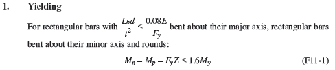
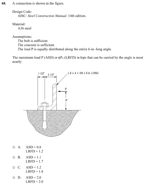
So there is this problem in the PE structural practice exam (NCEES). And I did my calculations and I'm not getting the same result.
2023-11-10_22_08_46-PE_Civil__Structural_Practice_Exam-2238929__-_Bluebeam_Revu_x64_cz22dq.png

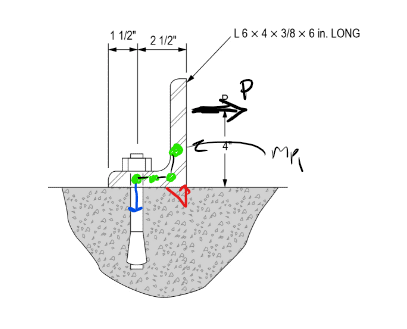
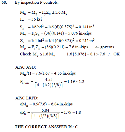
The "official" solution is this:
2023-11-10_22_23_59-PE_Civil__Structural_Practice_Exam-2238929.pdf_SECURED_-_Adobe_Acrobat_Reader_jgskgb.png


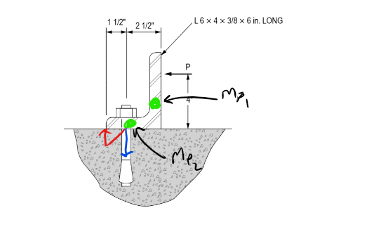
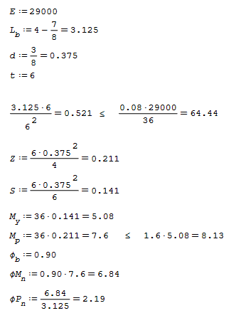
Now here is my approach.
This is a simple AISC 360-10 F11 Rectangular bar yielding check.
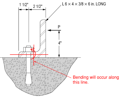
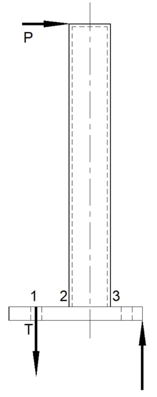
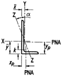
The leg that has the load will bend where the moment is maximum and the cross-section of the leg is smallest. This is at a distance k from the bottom corner.
So my calculation was identical to the "official" solution, except that when dividing the moment y the moment arm, I used 3.125 (4- 7/8) in stead of the 3.8125 (4- 3/16).
To me it just doesn't make any reasonable sense that the angle will bend at a thicker cross-section. I've seen the fabrication process for making 60-degree angles, and they always bend at k.
So I'm getting 2.19 for the LRFD result.
2023-11-10_22_16_19-SMath_Solver_1.0.8348_-_Worksheet1__dytnj7.png

2023-11-10_22_18_41-AISC_14th_Book.pdf_-_Adobe_Acrobat_Reader_32-bit_r9amls.png

2023-11-10_22_19_13-AISC_360-10.pdf_-_Adobe_Acrobat_Reader_32-bit_mtxnu0.png


There is also this topic, where a user takes a totally wrong approach by assuming the moment is applied at the outer face of the corner.

Am I missing something here?
 
Replies continue below

Recommended for you

confusing to show initial calcs that are not used ...

your final divisor "3.125" is not the same as their "4-1/2*3/8" = 3.8125 ...

"Hoffen wir mal, dass alles gut geht !"
General Paulus, Nov 1942, outside Stalingrad after the launch of Operation Uranus.
 
Thanks for the keen observation Sherlock, that is the whole point of this discussion. Maybe reading is too much to ask for in this forum?
 
The tension force would likely be a little more than 2.67 x P. For flexure, I'd use the plastic section modulus for the angle leg thickness... I wouldn't have even bothered to calculate Sx. You can work out whatever load factors or safety factors, accordingly.

-----*****-----
So strange to see the singularity approaching while the entire planet is rapidly turning into a hellscape. -John Coates

-Dik
 
Your calculation assumes the critical bending plane is in the vertical leg. There are two bending planes one in the horizontal leg due to prying action and also the one you have chosen for equiv. cantilever action of the vertical leg. Since the thickness and material are constant the critical bend plane is in the horizontal leg.

Screenshot_2023-11-11_040313_jr4l1e.png

Either Mp1 or Mp2 are sufficient on their own to create a mechanism and both are only influenced by P such that Mp2 will be the critical hinge.

If instead the loading was reversed then the compression block would sit in the heel of the angle and reaction formed there would influence the horizonal leg hinge points. Since Mp1 again is sufficient on it's own to create a mechanism and only influenced by P that becomes the critical hinge.
Screenshot_2023-11-11_035944_uaanmf.png
 
Often the critical load is at the hole location where the plastic section is based on the net 'width', including prying action.

-----*****-----
So strange to see the singularity approaching while the entire planet is rapidly turning into a hellscape. -John Coates

-Dik
 
"Thanks for the keen observation Sherlock, that is the whole point of this discussion. Maybe reading is too much to ask for in this forum?"

You're welcome Dr Watson.

I thought the book solution was obvious, mid-height of the flange (= NA of the flange in bending).
Your moment arm is the top of the flange. Why would bending at the top of the flange be critical ?
Yes, I missed your Lb ... you started with E, and I thought E? why E? It has nothing to do with either solution.

And I actually thought your "3.125" was just a typo of "3.8125"

"Hoffen wir mal, dass alles gut geht !"
General Paulus, Nov 1942, outside Stalingrad after the launch of Operation Uranus.
 
rb1952 said:
Yes, I missed your Lb ... you started with E, and I thought E? why E? It has nothing to do with either solution.
2023-11-12_17_25_11-AISC_360-10.pdf_-_Adobe_Acrobat_Reader_32-bit_jeer4e.png

Totally right, minor axis bending does not require this check, as yielding is assumed to control and not buckling.
Thanks,

271828 said:
Celt's sketches above are correct.
Yes, looking at this again, the horizontal leg experiences a larger moment and since it has the same cross-section, will control in regard to bending. Not sure why I missed that...

Celt83 said:
due to prying action
dik said:
including prying action.
Not sure what prying action has to do with the design of the connecting element since prying action only amplifies the load to the bolt. The horizontal leg could be twice as long, and the maximum moment in the horizontal leg would still be 3.812P. The location of the bolt along the horizontal member changes the load transferred to the bolt, but it doesn't amplify the force in the horizontal leg.

dik said:
Often the critical load is at the hole location where the plastic section is based on the net 'width'
If the bolt is assumed to be sufficient, then I think the "official" solution takes the assumption that the bending will occur on the edge of the nut, and not along the center line of the bolt hole.
2023-11-12_16_43_14-PE_Civil__Strucutral_Practice_Exam__Solutions__-_Bluebeam_Revu_x64_gz7edd.png


Thanks for the feedback everyone!
 
For guardrails, I check the hole location, the face of the post where the fastener is in tension and the face of the post where the edge of the base is in compression. The gross section is used at the post. I use prying action to determine the load from the fastener, as it affects the base design. It has no effect on the design of the post to the base, but can have an impact on the fastener design as well as the base design.

-----*****-----
So strange to see the singularity approaching while the entire planet is rapidly turning into a hellscape. -John Coates

-Dik
 
dik said:
For guardrails, I check the hole location, the face of the post where the fastener is in tension and the face of the post where the edge of the base is in compression. The gross section is used at the post. I use prying action to determine the load from the fastener, as it affects the base design. It has no effect on the design of the post to the base, but can have an impact on the fastener design as well as the base design.

I'm not sure I understood this, could you explain this with some sketches?
Thanks
 
yeah, but the OP is right. prying loads are not part of the solution since we're told the bolts are adequate.

what we do in real life is not assume the bolts are good, but prove it with calcs.

so, have we explained why your Lb is incorrect ?

being ignorant of your detail calcs, I missed your check (which is correctly done) to show bending stresses are critical.
It would've been nice to include the statement after the check (then us ignorant types would know what you're doing) ... and people checking your answer would understand the thought process.


"Hoffen wir mal, dass alles gut geht !"
General Paulus, Nov 1942, outside Stalingrad after the launch of Operation Uranus.
 

The prying load may affect the moment in the baseplate...

-----*****-----
So strange to see the singularity approaching while the entire planet is rapidly turning into a hellscape. -John Coates

-Dik
 
I'll get the right image, yet...

Clipboard01_ump0xg.jpg


-----*****-----
So strange to see the singularity approaching while the entire planet is rapidly turning into a hellscape. -John Coates

-Dik
 
understand, but in this specific case I don't think it does.

In this case the load creates the moment and the prying loads react it. Prying loads don't affect the magnitude of the moment.

In any case, we can see the answer, so we can understand the logic of it.

"Hoffen wir mal, dass alles gut geht !"
General Paulus, Nov 1942, outside Stalingrad after the launch of Operation Uranus.
 

They do a little bit at the hole location and increase the moment at 2 a little by increasing T slightly...

-----*****-----
So strange to see the singularity approaching while the entire planet is rapidly turning into a hellscape. -John Coates

-Dik
 
sorry disagree ... prying loads are a reaction to an applied moment (although I'm sure you can think of a scenario where that may not be as true as I think it is). They do (obviously) affect the moment distribution within the part, but not the peak moment ... unless you move the reaction points and so change the applied moment.

but this is al moot to the question posed.

"Hoffen wir mal, dass alles gut geht !"
General Paulus, Nov 1942, outside Stalingrad after the launch of Operation Uranus.
 
yeah that's on me I use prying to describe the type of motion the short leg is experiencing, need to get out of the habit of calling it that since it does not align with what prying action actually is.
 
try "bearing against" ? "pivoting about" ??

"Hoffen wir mal, dass alles gut geht !"
General Paulus, Nov 1942, outside Stalingrad after the launch of Operation Uranus.
 
Status
Not open for further replies.
Back
Top